Spot Welding Copper Strips to 18650 Battery Cells

BobBob said:
With a crimp the wire is supported at the ends and bending limited so the flex occurs in the loop.
1. With one or more strips, the mechanical fixing is via a tiny spot weld with perhaps 1% of the cross section of the strip so most of the strain may occur there.


i can glue the strip where it contacts the cells to help there


2. The flex and vibration are likely to introduce strain other than rotating around an axis through the centre of your looped strip. The strip will not bend as well if the cells move side to side or if the strp vibrates weirdly.

stress in other directions i think youre right and will put a lot of strain on connections...all i could do is glue the strip where it holds to the cell for more holding power. but the scenario under a skate deck velcroed in place should limit it to bending in the one direction.


3. The coiled coil high flex cable configuration means that the strand path is a tight helix following a more gently helix in the opposite direction following the path of the wire, supported by lots of other strands and all supported by insulation. imagine bending a slinky backward and forward until it snaps - you'd be there a while. Now imagine it was a straight piece of slinky wire - much more bend per wire section thus strain so if fails sooner.
The engineering complexity is way greater compared to that of the physics of bending a theoretical part and 3d.

im not seeing great engineering complexity and think the angle the material is bent decides how much stress it gets. the helix helps lower the angle any part of the material is bent as the bend is distributed, like a slinky as you say, but inside a wire isnt as wound as a slinky and often multistrand isnt wound at all so i dont think it's that important.

Bit of wire from an old robot cable I designed 20 yrs ago.
The previous chap used high flex but not for mobile (easy to bend once) and the strands had migrated through the insulation in a rolling loop and shorted to each other intermittently dependent on robot position (worldwide and intermittent)
Twisted twists.jpg

just as i see it. im no expert on wire but going with the simple understanding, which may not even be true, that the thickness of the material and how far it's bent and how many times decides if it will break
 
i didnt see your picture before
if you bend a wire you usually dont want to be tighter than 4-8 outside diameters
if your using 0.1mm sheet cant you fasten a 20 gauge/ 0.8mm copper wire to the fold/crease

or use 0.8mm x 8mm teflon tape
you tape it where you want the fold and fold over the battery

https://www.amazon.com/1800mm-cutting-plotter-protection-adhesive/dp/B078KW7L9T/ref=sr_1_4?dchild=1&keywords=plotter+cutting+strip&qid=1618024905&sr=8-4

14mm width would be better but only saw it in 0.5mm

https://www.amazon.com/3600mm-cutting-plotter-protection-adhesive/dp/B07282G5SP/ref=sr_1_10?dchild=1&keywords=plotter+cutting+strip&qid=1618024905&sr=8-10
 
i was asking about how stacking .025mm copper would compare to multistrand for a bendable spot. https://imgur.com/a/zgOZjfx

but think has run it's course and the fantasy is over. i made pcbs with fat traces on them for a flexible battery already and was just wondering what people thought
 
I might try it but I wouldn't trust it as much as high flex cable but I'd have to build it to really know
Hummina Shadeeba said:
i can glue the strip where it contacts the cells to help there[/size]
That should help a lot
Hummina Shadeeba said:
inside a wire isnt as wound as a slinky and often multistrand isnt wound at all so i dont think it's that important.
Sometimes it's important to choose the right wire but I'm just chucking ideas around for fun.
Hummina Shadeeba said:
just as i see it. im no expert on wire but going with the simple understanding, which may not even be true, that the thickness of the material and how far it's bent and how many times decides if it will break
An X is an unknown quantity, particularly online and a spurt is just a drip under pressure
Didn't mean to sound pompous, I tend to dive into detail
Completely agree, the copper crystals don't care whether they're in a strand or strip,
The glue or coiled coil reduce the stress.
 
I could use a little bit of advice on the copper sandwich method from those with some experience.

I'm planning to use a KWelder on a new pack to tackle spot welding 8 x .15mm nickel-plated copper strips, and it looks like the higher resistance nickel-plated steel is the way to go for the parallel connections/sandwiching technique.

I'm also planning on using the "infinite" slit method, so I'm wondering what thickness of nickel-plated steel would be best. I don't want to end up too thick that the welder has trouble.

It doesn't look like thickness matters so much when you use .10mm copper strips, but at .15mm - should I go with .10, .12, or .15mm nickel-plated steel strips?
 
spinningmagnets said:
Copper/Nickel sandwich thread with settings and materials
https://endless-sphere.com/forums/viewtopic.php?f=14&t=108006

Thanks, missed that. I didn't see anyone who has reported on using .15mm thick copper. I think I'll try the .10mm thick nickel-plated steel for the parallel connections. It'd be great to use those standard 2P tape/belt pieces atop the copper, but I chose an odd-sized 8x13 abs battery holder with 19mm cell-to-cell spacing and the only 2P connector option for that spacing is in pure nickel. Funny how that's now opposite of what I wanted 6 years ago building my first pack.
 
pbert said:
spinningmagnets said:
I am curious about any results you could post about settings for 0.15mm copper

Sure i'd be happy to do a test with 0.15mm copper. Ive ordered my copper from ali express so will take a month before i can get it and post results though. No worries for payapl, thanks for offer but i'm happy to contribute.

Ok so the copper finally arrived and it was worth the wait. I was able to successfully sandwhich the copper to the cell. Here are the details :

copper = 0.15mm
nickel = 0.2mm
spot welder = malectrics
spot welder setting = 26 ms pulse

The welds are solid and i fell better havin the 0.15mm than the 0.1mm copper even if the 0.1mm may have done the job.

@spinningmagnets thanks for the suggestion it worked out great.
 

Attachments

  • 20210508_000947.jpg
    20210508_000947.jpg
    183.5 KB · Views: 1,077
  • 20210508_001005.jpg
    20210508_001005.jpg
    145.8 KB · Views: 1,077
very nice!
the other advantage of using thicker copper is that i find the 0.1 is so thin that it has very little mechanical strength at the weld points.
I like to use 0.2 with a sandwich, and i can recommend the great welder i bought from diy dude in china,
https://www.youtube.com/channel/UC9_O7fpvfX-hhdoGLdNmnzA


check his store out-
https://www.yousun.org/
the 72mosfet version is good value at 80usd, and will do anything you need it to.
 
has someone done any A-B testing in how much you actually gain from this in terms of current load compared to 0.15,0.2 and 0.25 x8mm nickel with actual temperature measurements and (sustained) current loads?

this is very interesting in concept but we can all agree that its a LOT of work and added possbilities for breaking. so the gains do need to be noticable to be worth it.
 
i havnt done testing, but if you have say 120mm wide pack that fits in a frame and can't be wider, and you want to pull say 250 or 300A from that pack, i think it would be tricky to get enough nickel in there.

provided you have the right welder, its really not much work
 
ridethelightning said:
i havnt done testing, but if you have say 120mm wide pack that fits in a frame and can't be wider, and you want to pull say 250 or 300A from that pack, i think it would be tricky to get enough nickel in there.

provided you have the right welder, its really not much work

that is what i am interested in, the actual difference. so far the results are just academic. it would not be extremely difficult to slap a temp sensor on a strip and tape it down with some kapton and just go nuts on the current.

spinningmagnets said:
This is an awesome result! This is a new standard for high amp packs.

first we need to see what the difference actually is. so far there are several different methods and nobodt has done actual measurments.

i dont want to be the debbie downer here but i think its a little premature to go stand on a aircraft carrier with a "mission accomplished" banner without actually having the data....

we need to know how hot the strip gets between cells and how hot the battery terminals get on both sides at what currents and have some standard in the number of welds, metal thicknesses and so on.
 
"debbie downer" :lol:

what you say is so true. some cells from old necro power tool packs from the dump, reweld with copper , charge and let loose..
 
The area of concern is the negative end of the cell. As far as performance, 0.15mm thick copper has the same current-carrying capacity as 0.60mm thick nickel, with a much lower voltage-drop. (4:1 conductivity ratio between copper and nickel)

The copper also acts as a heat-sink for the cell. The heat permeability of nickel is poor. Nobody makes nickel heat sinks.

As far as heat damage to the negative end, it cannot be worse than spot-welding nickel, because copper melts at a lower temperature than nickel. It may take more current, but it's not the current that hurts the cell-end, its using too much heat.

The nickel cap has to get hot enough to melt the copper in two tiny spots, but the melting copper is not as hot as using only nickel would be. The nickel cap must get hotter than using only nickel, but the copper underneath it (copper nickel sandwich) prevents the higher heat from reaching the cell end.

After the copper melts "just enough" to bond with the cell-end, the copper dissipates that lower heat level faster than using only nickel.

When welding only nickel, the welding spots on the cell-end side get hotter and stay hot longer, compared to using the sandwich method. Because using only-nickel gets hotter and stays hotter longer, that heat is able to penetrate the cell deeper.

Nickel____1455C__2650F
Copper___1084C__1984F
 
I would like to know the difference myself. On my bike with the battery I built running a Nuc 24 I’m successfully sucking 250 amps out of it quite easily to peak at 17000 watts. The pack is a 20s15p 30Q with .15mm x 25mm pure nickel with 10 gauge copper soldered over the end strips that I meticulously built! We can argue on what it should or should not be able to do but I can guarantee what it does do. Unfortunately I have no way to test how hot the strips/connections/cells are. I have the ability to go up to 300 amps which I may in the future you to see if it makes a difference.......I fear that may kill the 3.5 QS205 V3 motor I’m Torturing with 250 amps?

That said, if I knew for sure with quantifiable results that the copper/nickel connections were 15% or more better I’d build another pack using that method. I mean real life what matters.....like longer ride time or ability to hold a higher voltage longer. Truth be known I’d like to go to the Molicel INR21700-P42A 4000mAh - 45a or Samsung INR21700-40T 4000mAh - 35A and just looking....er....hoping for a reason to switch to them but what I am using works perfect so far.

Tom
 
spinningmagnets said:
The copper also acts as a heat-sink for the cell. The heat permeability of nickel is poor.

…..
After the copper melts "just enough" to bond with the cell-end, the copper dissipates that lower heat level faster than using only nickel.
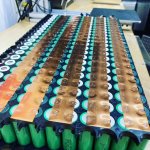
Very well said. Attached is a photo of the .25 mm thick pure copper busbars we use. We invested in a Sunstone Pulse Arc welder so we could use pure copper. Definitely a more expensive alternative but we are pleased with the results. as stated above, the heat dissipates very quickly when welding. www.vextrek.com AC9E5CF1-D685-4F3E-ACE0-A8C55ADF3824.jpeg
 
@garolittle: Nice looking pack - I'm curious: did you "dent" the copper over each cell (to conform to the outline created by the cell holder) with a small hammer or other tool? Or was the welding pressure enough to ensure the copper conformed as well as possible to the top of the cell?

(thanks)

EDIT: Actually, now that I look closer, it looks like the cells are actually flush with the holders. Very nice, may I ask where you got these holders?
 
Frank said:
@garolittle: Nice looking pack - I'm curious: did you "dent" the copper over each cell (to conform to the outline created by the cell holder) with a small hammer or other tool? Or was the welding pressure enough to ensure the copper conformed as well as possible to the top of the cell?

(thanks)

EDIT: Actually, now that I look closer, it looks like the cells are actually flush with the holders. Very nice, may I ask where you got these holders?

Good questions. The pressure from the weld head causes the indentations. We actually were able to spot weld .4 mm thick copper but the indentations were not as noticeable as one would expect. Those are regular cell holders that we simply turned upside down after boring out the “Tab‘s“ on the inside. This us to slide a cell in and out if it ever needs to be replaced.

Here’s a short video showing the .4 mm thick your copper bus bars.

https://youtube.com/shorts/ljw1OvuyC-0?feature=share
 
Frank said:
Good idea, how did you bore out the tabs?

Nice video on the website, BTW! :wink:

Thanks. :).

Used a 18.5 mm drill bit to bore out the holes. Took some practice to prevent from snapping the surrounding cell holders but after a while you get the hang of it. Great way to have a very flat surface for the cell holders and allows the bus bar to lie flush with the cell terminals.
 
Back
Top