• Hello ES! We could use some help to get us past the finish line on building the new knowledgebase for the forum.
    Can you donate? Please see our fundraising page. Thank you!

Sur-Ron - New Mid drive Bike

efMX Trials Electric Freeride said:
missed the Red Bull Tennessee Knockout TKO Hard Enduro??
her is your next chance to Race Electric:)..
SEER Going Electric!
SEER, South East Extreme Riders, Hard Enduro Race Series adds electric class.. :
SEER Racing is announcing a NEW e-Moto class in their hard enduro series!

eMoto-Class-TKO_Larry-Mayo-5.jpg


https://seer-racing.com/2022/09/21/seer-going-electric/

Sweet! I am going to follow this.
 
Rix said:
If you bought it new from Luna, they include a "tester" tool, plug that in to one of the harness plugs, and it will give you a blink code. Note what the blink code is, such as 2 fast 1 slow green/red, something like that, then contact Luna, and they will be able to tell you what the problem is.
Just curious: do they also include the codes with the tester? If not, I wonder why not?
 
stuntmanmike said:
Been a while since I’ve posted here, I bought my SurRon in 2018 after the initial rave reviews I read about here on ES and have never stopped mod’ing it, the only things I’ve left stock are some covers and trim, belt tensioner and the frame.
4ED99FAC-C69C-45C0-AECD-8BC8642C6F6E.jpeg
000AB8E4-50EA-4BE4-BC18-D7283E777DFF.jpeg
9CC73D57-4415-45DD-9EB9-0B2589C2E06C.jpeg

Beautiful bike Mike. Sur Ron's are a paradigm shifter.
 
amberwolf said:
Rix said:
If you bought it new from Luna, they include a "tester" tool, plug that in to one of the harness plugs, and it will give you a blink code. Note what the blink code is, such as 2 fast 1 slow green/red, something like that, then contact Luna, and they will be able to tell you what the problem is.
Just curious: do they also include the codes with the tester? If not, I wonder why not?

They did not include the codes with the the tester, when I was trouble shooting my SurRon, I called Tech support, they asked me to run the diagnostic and report what I observed. When I did, they diagnosed it as a "controller" problem and sent me a new controller. I did solve the problem.
 
Anyone try different Jackshaft bearings? NSK/FAG/SKF/etc? Hoping to find a set that lasts longer then the cheaper Chinese and Timken brands. Or if they wear just the same I will stick to the cheaper ones.


Some research shows that NSK Dynamic load is around 1060lbs and static load is 440lbs.

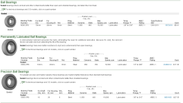
Not sure on the brand but mcmaster has these options:

bearings.png
 
Quinc said:
Anyone try different Jackshaft bearings? NSK/FAG/SKF/etc? Hoping to find a set that lasts longer then the cheaper Chinese and Timken brands. Or if they wear just the same I will stick to the cheaper ones.

Some research shows that NSK Dynamic load is around 1060lbs and static load is 440lbs

Looking to step up on bearing quality ?
Try these people :

https://www.bocabearings.com/
 
Quinc said:
Anyone try different Jackshaft bearings? NSK/FAG/SKF/etc? Hoping to find a set that lasts longer then the cheaper Chinese and Timken brands. Or if they wear just the same I will stick to the cheaper ones.


Some research shows that NSK Dynamic load is around 1060lbs and static load is 440lbs.

Not sure on the brand but mcmaster has these options:

bearings.png
SKF units are top notch. I always swap out the stock units on my DD hub motors for SKF units.
 
Does anybody know the pinout / wiring diagram of the surron programming/diagnostics cable? It has an LED that will flash out error codes. I lost mine many years ago. Trying to trouble shoot faults but don't want to wait around for shipping.

surron diag cable.PNG

https://lunacycle.com/sur-ron-diagnostic-and-programming-dongle/
 
I don't know of a schematic for the device or a code repository for it (most likely it uses an MCU you'd have to program correctly even if you built the device).

FWIW, according to another post about that device, even if you had the device, you have to contact Luna to find out what the codes mean (another poster said they don't give out the codes...though if anyone here that has ever gotten an answer from them about a specific code would post that code and the answer here, we could compile a list anyone could access. ;) )

https://endless-sphere.com/forums/viewtopic.php?f=10&t=89902&start=5750#p1734135
 
Code repository...programming a micro.... :roll: huh? You're over complicating it, lol.
It's just LED that blinks X flashes. LED blinks vs error code / meaning:
https://sur-ron.ch/pdf/Light_bee_L1e_blink_code_EN.pdf

I'm trying to figure what two wires the LED goes between. If there's some who actually has the harness, please chime in ;)
 
Ok. Sorry. Previous posters made it sound more complex than that, as if it were a custom device made by Luna, and also sound like the codes weren't available except from Luna.


Is there a pinout available for the connectors at either end of that cable? If so, I can at least guess which wires you can probably use to connect the LED to, if that would be helpful.
 
amberwolf said:
Is there a pinout available for the connectors at either end of that cable? If so, I can at least guess which wires you can probably use to connect the LED to, if that would be helpful.

Here's the pinout of battery 6-pin connector. I imagine the LED is wired from one of those Comms to ground, probably with a resistor in series. I imagine one could simply remove the tape on the debug harness and see how the LED is wired.
surron battery bms connector pinout.png

Reference
https://electricbike.com/forum/forum/knowledge-base/surron/147526-sur-ron-manual
 
Is the RS485 used for anything on the bike in normal operation? If not, I would guess that is more likely to be used for the diagnostic LED codes, presuming the comms lines are used to talk to a display. If the RS485 lines are used for the display, then the comms lines are probably used for the LED codes.

It should be relatively easy to find out which:

--if there is a simple way to cause a harmless error condition (like unplugging the throttle, etc) then a voltmeter (or LED with a 1kohm-10kohm dropping resistor in series with it to prevent overloading either the LED or any commline drivers in the circuit being tested) can be used between ground and each signal line in question, without disconnecting any of the signal lines (either probing from the back of the connector if you can touch the contacts, or poking thru the insulation of the wire itself).

If all you see on the voltmeter is about 2.5v, it's probably an active communications line with serial data passing thru it. On an LED it would appear to be a relatively steady dim glow (dimmer than when connected to 5v, anyway; it migh flicker a little depending on the contents of the datastream).

If you see a fixed voltage on the meter or steady LED on (or off) and you know it is (should be) generating a blink code, then it's probalby just not an active wire.

If you see a changing voltage on the meter (at the rate expected of the blink code), or the blink code on the LED, that's the right wire. :)
 
LED attached to RS485... what? :lol: I attached the full surron wiring diagram. As you will note, RS485 connects the battery, motor controller, and display on the same bus.

Reiterating, the LED must be connected some combination of those two Comm lines (purple or blue wires) and ground.

Yes i could start probing voltages in the harness. But would rather not play the guessing game. Hoping someone out there has the diagnostic harness and can simply look at the wiring of it.

surron wiring diagram.PNG
 
Sorry I couldn't help.

All I can do is provide educated guesses based on information presented and past experience as I don't have a Surron or it's documentation, and have my own stuff I'm working on so didn't spend time trying to dig up wiring diagrams.

Either serial bus is a viable option to output an error code on. Which one is used I can't know any more than anyone else without the specifics of exactly how this system works, or a wiring harness with the LED to measure or disassemble.
 
I don't have one of those either and would love to see the diagram to make one. It must be very simple. It just looks like wires, an LED and probably a resistor. There could be a jumper that enables the diagnostic mode, but I'll have to search again for the instructions on using it.
 
fechter said:
I don't have one of those either and would love to see the diagram to make one. It must be very simple. It just looks like wires, an LED and probably a resistor. There could be a jumper that enables the diagnostic mode, but I'll have to search again for the instructions on using it.

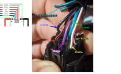
I was probing around with my oscope and found that purple wire, relative to chassis ground, blips up to 4.5V for 0.2s every 2s. This is considered one LED blink. If I unplug my throttle, I get 15 blinks = error code 211 = throttle short to gnd.

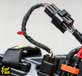
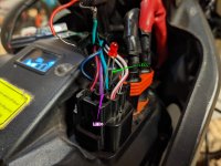
The purple wire has about 1.5kΩ of source resistance, so it's safe to wire an LED directly from purple wire to ground (picture).

I ended up permanently soldering the LED to the purple wire so that I can debug while out on the road :D. This should be a standard feature. How many peoples' surrons suddenly stopped working... and then start playing the whack-a-mole guessing game as to what might be broke. Hmm is it the throttle...kickstand...tilt switch...brake switch? Then start unplugging each to find out.

I have seen newer surron models on the internet with a fancy display that shows error codes. Nice. Where can we get that?

surron debug LED.jpg
 
Thx for doing tests and the slick mod idea.
This makes sense, because the diagnostic lead controller side purple wire, is not present on the battery end. :thumb:
 
Does anyone know how the change plug is wired? Picked up a CNLINKO LP-20 for my solar setup and figured I would ask before probing it. Thanks!
 
Pin 3 appears to be some kind of temperature sensor input that can stop the charger if the battery is too hot. The charger works with this disconnected, but you lose the overtemp safety feature.
 
Back
Top