Suzuki RMZ250 "E street" conversion

Jim Beagle

10 mW
Joined
Apr 12, 2024
Messages
27
Location
Port Charlotte Florida
Hello, lots of great info on this Forum, so wanted to share the journey of my build.
And if I get stuck, hopefully get some help, and maybe someday help others too....

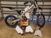
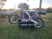
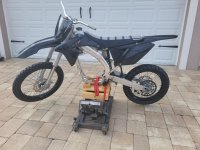
anyway, about a year ago, I bought this roller on Facebook, a 2015 Suzuki RMZ250 with an engine that was in pieces in a box. I strapped it to my bicycle carrier and brought it home to Port Charlotte Florida

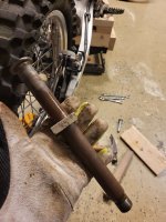
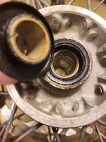
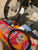
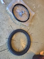
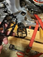
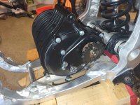
This bike was in really rough shape, but all the major components were there. I stripped it down to the bare frame, and cleaned, polished all the aluminum. A few of the smaller parts (wheel hubs, tank, brake calipers) I had a local shop vapor hone to also make them look like new. I replaced all bearings / bushings, and rebuilt the forks,
 

Attachments

  • 20240210_180314 original conditon.jpg
    20240210_180314 original conditon.jpg
    4.8 MB · Views: 17
  • 20240219_095103.jpg
    20240219_095103.jpg
    1.7 MB · Views: 14
  • 20240316_143231 frame finshed polishing.jpg
    20240316_143231 frame finshed polishing.jpg
    3.8 MB · Views: 8
  • 20240302_171606.jpg
    20240302_171606.jpg
    1.9 MB · Views: 9
  • 20240316_143231 frame finshed polishing.jpg
    20240316_143231 frame finshed polishing.jpg
    3.8 MB · Views: 9
  • 20240218_161241 axle bearings.jpg
    20240218_161241 axle bearings.jpg
    1.7 MB · Views: 9
  • 20240330_090640 rebuilt forks.jpg
    20240330_090640 rebuilt forks.jpg
    2.1 MB · Views: 15
I strung a new set of wheels, painted a few parts, and bought new plastics
 

Attachments

  • 20240320_203011  Wheels1.jpg
    20240320_203011 Wheels1.jpg
    2.1 MB · Views: 13
  • 20241101_173643 Wheels2.jpg
    20241101_173643 Wheels2.jpg
    2.6 MB · Views: 10
  • 20241120_190959.jpg
    20241120_190959.jpg
    1.8 MB · Views: 12
  • 20250110_140107 plastics1.jpg
    20250110_140107 plastics1.jpg
    4.8 MB · Views: 12
  • 20250110_140154 plastics2.jpg
    20250110_140154 plastics2.jpg
    4 MB · Views: 12

Attachments

  • 20250108_132038 Alibaba.jpg
    20250108_132038 Alibaba.jpg
    3.9 MB · Views: 13
  • 20250111_095408 lithium king.jpg
    20250111_095408 lithium king.jpg
    3.5 MB · Views: 14
Last edited:
Well, proper welcome on ES, Jim. I've been looking at your build on EDR; I've personally decided I won't cross post mine, but still good to see it progress.

The only thing I dislike about your choices are the tyres :D but as I understand it, it's gonna be more of a streetfighter/sumo street legal combo rather than an outright dirt bike.
 
my very own barn of batteries.......

here are a few boxes I built, but after all the back and forth with Amorge and various design tweaks, I think the max capacity I can get vertically between the frame rails at 72V is 12P (280 cells) Note: even with cutting off the bottom of the tank

here are three of my proposals to Amorge: Original V3, Empire State and Buffalo

Buffalo is three layers, and Amorge confirmed this would be 235mm wide. Two layers is 155mm wide

I was thinking if I go three layers, I should be able to get 20S 16P, as I have space for 112 cells on one layer
 

Attachments

  • 20250206_140157 batteries1 (1).jpg
    20250206_140157 batteries1 (1).jpg
    3.8 MB · Views: 17
  • Battery Design original V3.jpg
    Battery Design original V3.jpg
    176.9 KB · Views: 17
  • Battery Design Empire State.jpg
    Battery Design Empire State.jpg
    156 KB · Views: 10
  • Battery Design Buffalo v2.jpg
    Battery Design Buffalo v2.jpg
    188 KB · Views: 9
  • 20250112_182114 battery002.jpg
    20250112_182114 battery002.jpg
    1.9 MB · Views: 16
so this was the last couple of days with Amorge:

I sent the 'Buffalo v2" battery design to Amorge, Miranda comes back and says:
Hello, friend
We checked the size of your battery.
The 332MM position we drew only 323MM
According to the frame size of this battery, we calculated that there are 108 battery cells in total
In addition, if you need to make three layers, the size of the three layers is 235MM
In addition, this battery is a custom size, and the current size is not suitable for making a metal box.
In addition, you change the size of the battery to a rectangular shape, which is easier to make a metal box


I wasnt really surprised that they couldnt build a box with that many sides, and I was thinking maybe I could build my own, and good news she did confirm the width of three layer is 235mm and 108 cells. So I am thinking great 108 X 3 = 324 so they can do 20S16P. My sketch was 112+, so I am wondering if maybe I can pull in a couple of sides just a bit and give more clearance to the bike frame, and still have 108. So I asked how they came up with 108. She sends pic below with four cells crossed out, again I am thinking no worries. So I ask this question: What are the specifications for a 20S16P using Molicel P45B cells ?

and Miranda responds:
According to your requirement, 20S16P cannot be made.
The largest battery can be made to 20S15P
Because it is made by using three layers of batteries, then one layer has 7S, which is 16*7=112 battery cells, which has exceeded the battery size we calculated.
Making 20S15P is 105 cells, which is possible


Now I had 112+ cells in my layout, so I dont follow her 7S math above at all. and 20S15P should be 100 cells per layer not 105.

so here is where I am looking for experienced battery builders knowledge
can a three layer pack, share one set of 20S cells between the layers ?
100 + 110 + 110 = 320
or
107 + 107 + 106 = 320

Note: all of this has me seriously considering to just lower my expectations to 20S 15P, then shrink the size of a layer down to 100 cells, and possibly simplify the pack shape, so they can build me a box........

sorry for the rambling, but I appreciate the advice THANKS !!!
 

Attachments

  • Buffalo Mirand dropped four cells.png
    Buffalo Mirand dropped four cells.png
    601.6 KB · Views: 5
Sharing a parallel group across layers would mean more complex wiring. The bus plates normally connect twice the size of the group, i.e. for 15p that's 30 cells, half positive half negative. The last group has 15 and that ends with a large tab to connect to the first group of the next layer, so still 30 cells in total, just with a bend in the middle.

Typically they'll also flipped, so that the bend is as short as possible and the two groups of 15 can effectively touch. Now if you tried to move some of the cells to the other layer, you'll have to wire their other side all the way around the pack, and that would be super impractical.

The battery I bought is wired with copper braid and does such internal routing but I don't think it's a good idea at all.
 
…more amore’ for Amorge

For the last couple of weeks, I have been going back and forth with Miranda. I would get a bit frustrated with the language translations, but she has probably been equally frustrated with my lack of battery building knowledge and endless questions and multiple design tweaks…. With each of my proposed designs, I would build a box from heavy duty cardboard to test the fitment in my open frame area

After the Buffalo cell layout, I thought I would see what were the options for having Amorge build a three layer steel box. I proposed this simple five sided shape, but Miranda said they would have to cut off the bottom triangle. With that in mind, I sent over the five sided Penta Wedge. She said they cannot build a box like that. At this point I realized a box built from Amorge just wouldn’t give me the total quantity of cells that I was hoping for.

Miranda and I discussed BMS location, because depending on the layout, I would lose a row or two of cell count spacing. (see the BUFFALO above) I asked about an “external” BMS, and she came up with the idea to mount the BMS on the “side” of the pack, which increased my width from 230 to 255mm. yes, this is close to the overall width of my RMZ frame, but I was OK with that.

So I played around with various cell locations and different shapes and angles, and sent over the MEGA design. This layout was 20S-17P with 119 cells per layer 7S+7S+6S 119+119+102=340 cells. This was really pushing the size envelope and I was worried that I might not be able to build a box around the pack and still squeeze it all into my frame. Miranda also needed to increase the size in a couple of areas.

So I pulled back one more time and went for a 20S-16P design 112+112+96=320 cells. I called this final proposal MABEL, which was my grandmothers name. With just a couple of minor tweaks, I was able to come to an alignment with Miranda on the pack size and shape, and still have some wiggle room to build my own battery box. HURRAY !
 

Attachments

  • Amorge5 cut bottom off triangle.png
    Amorge5 cut bottom off triangle.png
    39.7 KB · Views: 6
  • Amorge5 PENTA WEDGE.jpg
    Amorge5 PENTA WEDGE.jpg
    130 KB · Views: 6
  • Amorge7 MEGA 2017 v2.jpg
    Amorge7 MEGA 2017 v2.jpg
    178.7 KB · Views: 8
  • Amorge8 MABEL 2016 v4 Final.jpg
    Amorge8 MABEL 2016 v4 Final.jpg
    155.6 KB · Views: 7
Admirable tenacity. Building your own box gives you insight into how the battery is protected and insulated, which I personally value over trusting someone else to do the job right. 320 cells is still going to be plenty fine.
 
My original battery choice was going to be Molicel P45B, but after a bit of research I am leaning more towards the Samsung 50S.

SAMSUNG 50S: HOT GARBAGE OR MISUNDERSTOOD GEM?

According to people much smarter than me, the Samsung peak amps is very overstated. But I am willing to trade max power for more range, and with 16P and 320 cells, I doubt I will be pushing/pulling this pack very hard

So here is my final quote from Amorge for the MABEL pack, but I would appreciate some advice before I pull the trigger :)

I have seen other Amorge quotes that indicate an 84v 10A Charger coupled with a 72V battery, my quote says 72v,
should I request a different Charger ?

I also have seen the description for “open discharger”
should I request this option ?

Miranda also says: Regarding the output cable, we recommend that you use a dual QS10 connector so that you can fully utilize the continuous current you need. Because no connector can fully use the continuous current of 400A. The cable on my battery is 20CM, and the normal one we provide is a 25CM ring terminal I will check these lengths,
any other advice here ?

thank you all for your help!
 

Attachments

  • AmorgeQ cell prices 20S16P.jpg
    AmorgeQ cell prices 20S16P.jpg
    55.1 KB · Views: 7
  • AmorgeQ Quote.jpg
    AmorgeQ Quote.jpg
    234.3 KB · Views: 8
What does open discharger mean?
Is that no main contactor? Or if more expensive, more current capacity?
 
84V is the voltage used to charge a 20S (nominally 72V) pack during the last CV stage. I can see why those values would get mixed up.

Open discharge could indicate a BMS bypassed for discharge, or something different. What was the context for that?
 
from Don Cox on another forum:
Open discharge puts less heat in the battery. It already builds heat, and the Discharge MosFets add more. The controller will shut it off at 60V or whatever you set it to be. Then keep an eye on the BMS for suspicious cell groups.
 
Yeah, that would mean the BMS wouldn't be able to actually cut the battery off, unless you wired it through e.g. a BMS-controlled contactor.

It means you get no over current protection, no short circuit protection, no automatic pre-charge and no way to safely work on the vehicle with the battery plugged in. But yeah, perhaps a bit less heat too.
It also means no cell-level LVC, so any cell imbalance could lead to cell damage (whcih can then lead to a fire) if you run the battery down enough to push the lower cells below their safe limit.
 
so yesterday I received this email and about a dozen pics from Miranda at Amorge

Hello my friend
We have created the battery, please check if it is suitable for your frame?
If it is suitable, we will ship it to you


all of the dimensions checked out, a few were actually a bit smaller, and just two weeks after I placed the order ! (y)
 

Attachments

  • unnamed00.png
    unnamed00.png
    310.6 KB · Views: 17
  • unnamed03.jpg
    unnamed03.jpg
    404 KB · Views: 16
  • unnamed05.jpg
    unnamed05.jpg
    501.8 KB · Views: 16
so I'm looking at my wiring harness

The three speed plug connection
Harness drawing says
Pink..................Third gear
Green................GND
YellowWhite......First Gear

The throttle sheet says
Blue................Low Gear
Gray................Input
Orange...........High Gear

Point #2 at the top of the T08 throttle sheet says: The color of the corresponding wire may change. You only need to disassemble the handle when installing, and you can see the wiring at the corresponding position to be clear.

Both plugs are wired per their respective diagrams, but it looks to me like the Hi & Lo wires are backwards.

Should I just plug it in and hope the smoke stays inside ? ;)

Or swap the wires ?
 

Attachments

  • 20250330_151412.jpg
    20250330_151412.jpg
    481.9 KB · Views: 2
  • 20250330_151432.jpg
    20250330_151432.jpg
    907.1 KB · Views: 2
  • 20250330_151440.jpg
    20250330_151440.jpg
    813.5 KB · Views: 2
Just to be sure: are you trying to connect a throttle to the three speed switch connector on the controller?

If so, that won't work.

If not, it's best to state exactly what you're trying to connect, and to what.

Your present info isn't clear, but *could* be a throttle with a three speed switch built in... If this is the case, you'd need to be sure that the wires you're using from it to the controller are the right ones for each part--there will be three for the throttle, and three for the switch, normally.

If it is a 3speed sw, you can verify which wire is which by using your multimeter on continuity or ohms; it will get a "zero" reading whenever you are connected from the center of the switch to the side that is turned on, and "infinite" or OL or -- (depends on your meter; check it's manual) to the side that is not turned on, or if you are measuring from one side to the other.
 
Thank you Amberwolf for the advice

Here are more pics of my harness, throttle, and schematics
 

Attachments

  • 20250331_141457.jpg
    20250331_141457.jpg
    1.5 MB · Views: 3
  • 20250331_140955.jpg
    20250331_140955.jpg
    2.4 MB · Views: 3
  • 20250331_140740.jpg
    20250331_140740.jpg
    1.4 MB · Views: 3
  • 20250331_140732.jpg
    20250331_140732.jpg
    1.5 MB · Views: 3
Yeah, that combination switch should have a three-pin connector for the mode switch and a three pin connector for the analog throttle input - but I see it seems to combine the mode and S/R buttons into one larger connector. It's very easy to verify it passively with a multimeter by plugging in and operating it.
 
Back
Top