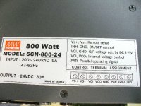
Meanwell SP-320-12,24,27,36,48
Wednesday, March 03, 2010
9:50 PM
[ General First Impressions ]
I have now spent about 6 hours of research and reverse tracing of the circuit (SP-320-24) and have made little headway but it's not immediately encouraging.
These units alone (not with an S-320-X) may well be a TOTAL waste of time (unless we can increase the FAILURE delay very considerably on the MCU (should be a resistor / cap (RC Charge/Decay time) which set this failure response time).. It may be that by increasing it to the point where maximum output current is reached (assuming it doesn't jump above 130% of 350w) it will prevent the automatic shutdown; add CC/CV control via external shunt monitor and FET gates which limit current (but will also suffer from heat dissipation (though pulsing in ON/OFF mode may not be such an issue… must calculate voltage drop and losses.)
[Tonight's Quick Test]
So, I will try to connect one of these SP-320-24 up with a modified 48v unit S-320-48 in series, set to 62.25 - 24 = 38.25v (might need slight down voltage mod.)… 350 / 34.25 = 10.219 - since we want a 1C charger for 10AH pack… 350 / 10 = 35v, if this works correctly then we will have the S-320-24 set to 27.25v - normal 100% rate for this would be 312 / 27.25 = 11.4495 A, the above in series should limit the output power to a mere 10.219v if it will be successful mating of the two (not even sure if it will work but by default 2 supplies in series should (best as I know) limit to the lower of the two outputs ) then problem is 1/2 solved (for those of us having some form of S- version with shunts or other method of measuring output current side).
I hope my only potential issue is the voltage will drop down to that of the 48v unit (41.5) which I can then use as a 10A 41.5v 10S bulk charger… this will be useful in the near future since I am working on a delta/wye geared hub drive system which should be promising to say the least! The voltage drop would be the 24v unit not following with the current limit of the 350w charger. The 24v unit will be set for 5 * 4.15 = 20.75 v which means it could output 312 / 20.75 = 15.0361 A continuous (shame it won't work without CC limiting… wonder if 2xSP-320-24s and a single SP-350-24 configured for 15A would properly limit the SP-320s to 10A for 240w each… total power 240 + 240 + 350 = 830 watts for a 1.5A charger.
350 / 10 = 35 / 10 = 3.5… this means from the time the unit reaches 3.5v per cell we will be at 100% of rated power… if we move along and look for the nominal pack voltage of 37v we will only be at 370w which is just 20w greater than nominal 100%.
I believe the idea here is…. The bulk of the charge process happens between 3.5 and 3.9/4.0v per cell so 40v would still require full power or 400w… these are peak rated at 130% (I've run the farther) so 350 * 1.30 = 455 watts… the maximum we reach is 415 is only 118% of the charge cycle and it will last (on a 10AH pack) just a few moments (with the fan on mod, shouldn’t make a difference) before taper off begins and the power begins to fall below the 350w range.
If the 2 x S-320 + 1 x S-350 works properly in series than a simple 15A charger should be possible:
312 / 20.75 = 15.0361 A (below 130% so shouldn't trip but, best would be to set the S-350-24 at a maximum of 15A just to be safe - this is well within the 350w limit / range and will allow for a true 1.5C charger to be created - consider 40m full recharge times for an 30 - 60m of ride time at 20-45mph.
I will report back my findings in combining with other S-350 units (as I believe I did this early on and it worked okay!).
I have also sent another email to Meanwell Support - I went right to Meanwell China Corporate this time as the USA branch had been less than helpful in the past…
Upon comparison of the board layouts, it's a shame if this had current limiting too… that would be perfect for our uses because other than the lack of the output side current limiting these are designed better than the S-350-X units (imho).
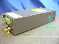
I've inquired to MeanWell to clarify the differences and availability on the S-350 / S-320 / SP-320 models and also explained that our (collectively, myself as a commercial customer and also representing a large body of potential clientele, i.e. the community here on ES) requirement was for Current Limiting design which would handle these loads properly and or adjustable between say 50 to 100% range or even 100 - 130% limiting factor (of output rated power)…. Also I have inquired if there is a possible mod we can all made to our supplies to disable the over current protection (which should result in the case of over current in a blown fuse so all is good there too) since I believe without the hiccup mode it will fallback to delivering the maximum rated output 130% based on AC input current (eliminates the need to monitor the output stage and also) and simply PWM the output to maintain acceptable limits on the AC side… the only issue I could foresee there is the use of 110/220 with these devices… but there is a switch and I suppose a dual limiting circuit must already exist on this bus.
Fechter and Jeremy Harris really are still deserved of the credit for the concept of hacking power supplies into chargers (yes methods too) and they are much more adept at circuit analysis and hacking than I am… Perhaps one of them have some suggestions as to the best route to investigate with these SP-320s to get them at least not useless!
REQUEST: ** If anyone has an S-320-48 they would part with, I would be more than happy to purchase it and pay for shipping… that's an S-320-48, I believe they have shunts and I don't have one here at the moment but I would like to source a sample here in the states rather than from China… (for a reasonable price obviously).
[On going ideas]
Since I know many of us have purchased SP-320-X supplies (myself included) the ability to add true Output Current Limiting by adjusting the PWM of the conversion stage if the above does not work will be the only salvage for these units (other than eBaying them off, but
There are other methods which would involve linking the clocks of two or more supplies to sync the PWM timing… this will result in (I think) less ripple and noise but are IC specific.
One further option (something I did with the SP-350-48 when adding an MCU) would be an external shunt (sure-electronics.net / sureelectronics.net has up to 100A/100V units) and a resistor bridge to bring the voltage within the 5v range needed by MCU A2D… then using one of the MCU outputs, adjust the duty cycle to limit the current to within the allowable limit (ie: 312w @ 48v).
[ Final Comments ]
I have contacted several overseas charger manufacturers and the largest issue with their offerings is they are not modular, cannot be reconfigured as your packs grow, have non programmable charging curves / characteristics and worse they seem to have a bunch of drift:
One other issue with the available chargers is unlike a Power Supply…they can't be easily hacked to various different voltage and only have at most 3 voltages possible selectable via a switch (which I assume could be expanded)… An additional feature lacking in all these is a simple 5v style return loop where a connected BMS could request between min and max (0v = nothing, > 0v = min = 5v = max) current limiting which would be instrumental in allowing function with any standard BMS available (even something as horrible as CellLog8s).
[CellLog8]
With regards to the cell log 8s…. We need 1 or more of the following things done with this product to make it truly useable for our purposes:
[ Consumer Required celllog8 Changes ]
To make the CellLog8's useable for LEV/EV/eBike and Larger RC applications to be used / doubled as a BMS brain, the following issues need to be addressed and the more critical ones need to be solved… some are just niceities and some are for consumers / while others are for pack builders (who isn't some form of pack builder, RC or other hobby?).
[Required Changes]
1.) CellLog8 needs to draw power from as many cells as its connected to instead of just 1-6. Useless for the purpose of monitoring up to 16S pack (or 8 or 24S) because the draw on 4 of each 6 cells in the pack will be discharged unevenly due to the consumption of the CellLog8.
This is a known issue with them and it has been addressed (sort of) in the rc forums, I have attempted to figure out the "work around" but then I see people reading the wrong cell voltages after they do the mod to enable use of the entire 8S as a power source….
An 8S cell logger does not much good if it takes a pack out of balance on it's own (no matter how slowly.
This limits the CellLog8 to nothing more than a 6S maximum logger (where it consumes power from the entire pack). 6 * 4.20 = 25.2 v 8 * 4.20 = 33.6 maybe it has something to do with the base voltage of 6S vs 7 or 8S (33.6v) and the internal regulator chip can't handle the 33.6v… I think the solution had something to do with adding a resistor to the 7 and 8 cells which drop our voltage to where the A2D reading of cell voltage can be taken and that results in incorrect readings.
2.) Requires better alarm output - To be integrated as part of a BMS section this output will need to be extended into 3-4 ways - I have no idea the code behind these so I can't really rank them in terms of ease of implementation but I can venture some guesses:
[Method #1 - Separate Alarm Outputs]
For end consumers (RC, LEV and eBike, eConversions) and system designers / pack builders, BMS and other type systems having the outputs opto coupled would eliminate the inability to parallel them out of box.
Required individual alarm outputs should be:
a.) Cell Low Voltage (LVC) Alarm
b.) Cell High Voltage (HVC) Alarm
c.) Cell Out of balance Alarm
d.) Other Alarm (could be the optionals from below).
Optional alarm outputs (useful but not needed for working product):
a.) Pack High Voltage (HVC) Alarm
b.) Pack Low Voltage (LVC) Alarm
c.) Timeout Alarm (useful for conducting testing)
[Method #2 - opto-coupled RS232 (TTL Level) Direct (preferred opto coupled for isolation) before the TTL -> USB (or atleast proper vias to tap into TTL TX and the TTL common GND and VCC - we can add our own client side opto coupler)]
This may be the most cost effective and ROI on an upgrade/mod to the cell log 8 for your company to make… it would require nothing more than a simple modification to the PCB to include traces with vias used so system builders or advanced users could tie these together for the purpose of receiving data from multiple units via an mCU - this would be the truly advanced method but - it would also allow your company to develop a single Atmega32 (likely, same as in most of your other products) which receives and collects (via opto-couplers on the board if not included with the CellLog8s) the data and either loggs or do the good old Eagle Tree Route and sell the Data Logger separate from an LCD screen (please, simple… water proof and backlit).
[Method #3 - Pulsed Alarm Output]
Could be the truly most cost effective method of adding advanced ability without altering the circuit (much, assuming the MCU trips and holds the alarm and could pulse the line?)
Here you would simply add an option under "Alarm Output Options" and instead of just NO and NC… add Verbose_NC and Verbose_NO. That option would indicate that the output is to work under NC/NO just like the normal settings but instead of latching until condition clears… the line pulses the error code (think old fashioned OBD2 diagnostics plug on a chevy, short 2 wires with a paper clip and the Check Engine light would flash a bunch of times (9 in some cases) then a pause (notable by lack of flash) then a second burst of flashing (let's say 2) - that indicated error code #92 which I can't remember what it was now but… this would work perfectly with both novices / normal RC people and LEV/EV crowd too… For the first group (generic RC) the circuit they would drive with their CellLogs would be latching - first pulse would latch it. A button to reset (think bathroom GFI outlets). The second group would have no issue building either a simple analog circuit which counted pulses (much faster than the Check Engine light) and then when Next Number Timeout (too long for next sequence) (or better after receipt of second digit) the system (analog or digital) would examine the code it just received and apply it to a form of look up table and use that to direct the proper error action.
[Interlinking]
Instead of redesigning a great product… why not an isolated data link between then so that they can be installed in series and recognize total pack volage and cell level variances across packs they are connected to.
That's my .02 - I'm off to bed.
-Mike