The Barncat Battery- No weld/no solder

I'm all for anything that makes it easier to swap cells, though the trick is in the details. Low voltage, high amp contact connections can easily become high resistance. And we know what happens then.
 
Fairly close to buttoning this pack up.

Sprayed some rattlecan on the sidewalls, preassembled the tensioner screws/nuts. Because the copper screws are being used opposite their normal direction, each end must be carefully offhand slotted with a dremel and thin grinding wheel to accept a small flat blade screwdriver.

All the new cells are laid out and checked for voltage. A dozen or so were .01-.02V under and were quickly matched up with the simple charging jig shown. I trim the overwrap off the negative ends for maximum contact with the braided straps.

Third pic shows some of the grid pattern of 1/8" holes drilled in the right sidewall. These are exactly positioned to insert DMM leads to monitor voltage of each parallel group.

Some work to do on the lid, and the two 8ga leads to a QS8 connector.
 

Attachments

  • 20240224_173903.jpg
    20240224_173903.jpg
    3.5 MB · Views: 28
  • 20240224_173952.jpg
    20240224_173952.jpg
    1.7 MB · Views: 29
  • 20240224_174116.jpg
    20240224_174116.jpg
    1.6 MB · Views: 30
  • 20240224_175850.jpg
    20240224_175850.jpg
    8.1 MB · Views: 27
Pretty much done. Just need to drill 4 holes in the base for mounting on the bike, and have to solder up an adapter plug for the charger to QS8.

Anyone know whether amp output is adjustable on this charger? Voltage is, but current probably not... (edit- the current can be adjusted but it's already nominally maxed out at 3A, 84V with a 240W rating...)
 

Attachments

  • 20240227_170914.jpg
    20240227_170914.jpg
    3.2 MB · Views: 25
  • 20240227_170829.jpg
    20240227_170829.jpg
    1.6 MB · Views: 23
  • 20240227_170759.jpg
    20240227_170759.jpg
    1.8 MB · Views: 26
  • 20240227_160648.jpg
    20240227_160648.jpg
    1.6 MB · Views: 29
  • 20240227_175620.jpg
    20240227_175620.jpg
    6.8 MB · Views: 26
Last edited:
Really like the look (fit), practicality of your earlier (COG) location for ride safety ...
1709152073943.png

Don't see this battery location as practical IF that's how you now plan to locate your 21700 battery ...

1709152373406.png

Are you making a lengthier custom frame with seat a little closer to handle bars (see top photo)? Really like to cool-look of the top bike design ... not the top heavy design.

Have you yet arrived at a custom bike frame design that's the best fit for your heavy 21700 barncat battery?
 
eMark- the green Orange County Choppers Schwinn is an unusual frame design that lent itself to the low battery/motor/controller mounting setup.

My 4 other builds all required putting the battery pack on the top tubes as they wont fit inside the triangle. They all handle great, the mass (12- 16 lbs) relative to one's torso is insignificant; all motorcycles have gas tanks in that arrangement. Aesthetically I suppose a triangular pack is preferable with bicycle conversions, but not possible with my design.

I had planned on building a custom aluminum full suspension frame using 1 x 3 rectangular tubing that would look similar to the Mongoose Blackcomb. The battery would be hung from a fairly horizontal top tube to look more integrated with the design, with a motorcycle style monoshock swingarm. Not going to get to that this FL season. I am going to try to build a sprag bearing freehub 24 inch rear wheel however...
 
Last edited:
EDIT change from yesterday ....

Does your battery design NOT lend itself to any existing rear hub/pedal ebike design? Getting the impression you like to fabricate your own creations ... whether it be a new battery fabrication or redesigning an ebike frame to your specification.

Like you and a few others i'm also my own BMS (don't trust them) ... so can understand one reason for your non-BMS battery fabrication for ease of removing/replacing a weak/bad cell.

That said, doesn't removing the crank/pedals become illegal as a Clsss I, 2, or 3 ebike. What do you have against a rear hub motor and pedal power when needed as less desirable than your ebike motor/chain drive design.
 
Last edited:
You're correct to assume I'm strictly a DIY builder.

When i was younger i built 3 different recumbent bikes from scratch, then years later designed and built a run of a dozen full suspension mtb frames from 7005 Easton aluminum tubing, including fabricating a large 500F oven to heat treat them in. Over the last 20 years I've built about 20 70's era Japanese cafe racers, but the supply of donor bikes pretty much dried up, so i switched to ebikes, with the same minimum weight maximum speed aesthetic.

IMO, hub motors are not only too heavy, but the weight is in the wrong place. Also after decades of serious cycling i can no longer sit on a conventional bicycle seat due to minor nerve damage, hence the flat platforms... so pedaling is out. I use inline skates for exercise.

Class 2 ebikes without pedals are legal up to 20mph. I keep a sharp eye out for the police (whom i support and respect btw) and hug the shoulder at under 20 whenever i see a cop car, though they don't really care anyway fortunately, in my experience. I have never once been stopped in thousands of miles either here in FL or up in our small town in east TN. Just use common sense. I always carry my drivers license (with motorcycle endorsement) as a potential bargaining chip just in case.

New pack on the charger ready for maiden voyage.

(Edit/update- this battery was well worth the build. I'm running 220 phase amps/140 battery amps into a Flipsky 75200. Target max of 60+mph achieved, with a 65lb bike that cost around $1400 in parts.)
 

Attachments

  • 20240301_132830.jpg
    20240301_132830.jpg
    2.4 MB · Views: 32
Last edited:
I think there is a huge market for a power back-up pack for a home, in the 48V-52V range. When everything is going well, we might use "X" amount of kilowatts of energy each month, but I live in tornado country, and it's not unheard of for a wind-storm to knock out power for days, if not weeks.

In that situation, the average person will suddenly re-prioritize their power needs. If someone needs to refrigerate their insulin, then a chest fridge can be a low power device to act as a refrigerator with the temp adjusted to the proper range, and air conditioning can be secondary. Such a person might find themselves using 1/10th the amount of energy they normally would use, but it is the most vital tenth.

I have recently moved, and one of the new purchases was a large chest freezer. Since cold sinks, having the opening on top means that frozen foods can stay frozen for a VERY long time after the power goes out. Even after the frozen goods start to thaw, they are still cold enough to remain unspoiled for an extended time.

A DIY battery pack using pressure contacts is a fantastic home back-up. There is a reduced risk of contact corrosion, and there is no heating-cooling cycles (like a garage) and there is no vibration of sudden pothole shocks.

I want endless-sphere to be the hub for this type of information. If this design works well for Barncat's ebike, sweet. But even if it has enough issues that he upgrades one part of it, the pics and the discussion are saved here for thousands of readers, who will come here because of a google search on this subject.

speaking of home powerwalls, here's mine - 13S/160P, approx 23kWh, double-sided, all recycled 18650-ies, not welded but in batt.holders for ease of exchange.
 

Attachments

  • el taller pw.jpeg
    el taller pw.jpeg
    762.3 KB · Views: 37
this is a fantastic life extension for old cells. Especially for the unweldable kind, like Tesla's
 
speaking of home powerwalls, here's mine - 13S/160P, approx 23kWh, double-sided, all recycled 18650-ies, not welded but in batt.holders for ease of exchange.
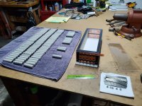
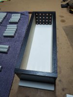
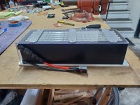
Great idea! Can you tell us how you built the battery holders? Are they charged by solar or the grid?
How is it performing?
 
i bought d batt.holders, see pic. i am charging 99% by solar, but still have option to connect to grid for back-up.
 

Attachments

  • cell holders 2-4.jpg
    cell holders 2-4.jpg
    58 KB · Views: 9
i bought d batt.holders, see pic. i am charging 99% by solar, but still have option to connect to grid for back-up.
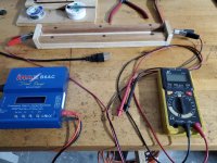
How are you monitoring the cells? What kind of BMS?
Is the power wall in a separate shed, away from the house?
 
ANT 300A
MAX7200 (Voltronic) Invertor/Controller
the PW is in my work-shop, no separation possible.
 
Last edited:
raedy07- good that your large powerwall works well and that you utilize "free" solar. I've got a great site for that here at the FL house but I'm too nervous about having that much lithium attached to it... plus the building code people are very difficult, plus hurricanes...

Back to ebikes: as an update I'm pleased to report that my 3 Barncat batteries have functioned very well over a total of probably 8000-9000 miles on 5 different ebikes, 2 of which have no suspension, 1 has an air fork, the other two are full suspension. Mainly road use as intended with some gravel, but they've been subjected to all manor of bumps and vibration, and some hits hard enough to snap the zip ties that hold them to the frames. The cell groups need to be manually monitored for voltage balance but they self balance well. It's advisable to start with brand new cells. I usually disassemble a pack once a year or so to check everything and readjust. And I never ride in the rain- getting them wet is not a good idea, though a simple fabric waterproof cover could mitigate that.

I have 100 new Samsung 50s 21700 cells arriving soon to build another 20s5p pack basically identical to the one in my last post above on this page. The 5000ma capacity will add several miles to the already good range of the p42a pack, and the 25A rating with higher bursts is more than enough current.
 
I'm finally getting around to my 4th pack build. 20s5p. It'll be just 4s long this time with 5 layers, that fold back on each other in alternating polarity as is required with my design.

Built the case today. Tolerances must be exact as usual. Still some tricky work to do to drill and install the threaded inserts on the business end wall that does all the compression.
 

Attachments

  • 20250219_111224.jpg
    20250219_111224.jpg
    1.8 MB · Views: 10
  • 20250219_114357.jpg
    20250219_114357.jpg
    1.8 MB · Views: 9
  • 20250219_140644.jpg
    20250219_140644.jpg
    6.9 MB · Views: 9
  • 20250219_192102.jpg
    20250219_192102.jpg
    1.6 MB · Views: 9
  • 20250219_192118.jpg
    20250219_192118.jpg
    6.8 MB · Views: 10
  • 20250219_214004.jpg
    20250219_214004.jpg
    7.8 MB · Views: 10
I've just discovered this thread. First and foremost, thank you for sharing your results and designs with the community.

There's been a growing demand for battery enclosures that hold the contacts mechanically. While I don't believe it would be sufficient for the true capabilities of the cells (currents of 25A and above), it looks like an interesting and sustainable option for lower-power vehicles.

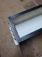
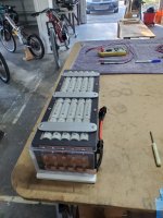
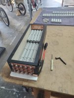
I don't believe a BMS is necessary. I'M the BMS. There is instant DMM access to each parallel cell group down one side to check voltage and at the ends for pack V.

This I disagree with, though. "Instant DMM access" is great, but what you want is continuous monitoring during use. I believe a lot of people focus on the balancing aspect of battery management, which itself isn't particularly useful. Monitoring cell groups for anomalies during use (such as when something breaks contant and starts discharging a group disproportionately), monitoring battery temperature in multiple places, and monitoring and shutting off the current out of the battery, continuously, is not something a human operator can do, not nearly fast enough (based just on external behavior) to react to something abnormal happening. At the very least, you should be aware of those parameters by monitoring and alerting, but at that point it's actually cheaper and easier to simply use an off-the-shelf BMS.

In fact, I believe a lot of concerns of people worried about the performance of this construction can be proactively answered by using a BMS that guarantees safety in case any of the potential failures happen. I.e., not saying that failure is impossible, but merely highly improbable, and still having provisions for when something happens.
 
bananu7- please see my notes below re amp settings. I'm running 150A battery on both my Molicel p42a packs, or nominally 30A/cell, and could easily go higher, up to the rated 225A for the 5p configuration. I'm staying conservative since the suggested Flipsky 75200 controller continuous ceiling at 20s is 150A. Trust me, my Hyper29er build is pretty darn quick at those settings. Raising the amps would only bump the torque a bit not top speed of course. I could certainly up that max setting- 75200's are really inexpensive, and we're talking bursts here not continuous.

Yes, I made my opinion re BMS clear back on page 1 of this thread. Anyone is free to differ. As I like to say, 'the chance is greater than zero' that one of my packs could develop a problem, and also that a BMS could fail. Since my design allows for complete disassembly of all cells in about 10 minutes, it would be impractical to solder a rat's nest of thin wires to each parallel strap from a BMS. I'm willing to spend one or two minutes prior to each ride monitoring a few voltages. I also never charge the packs unattended, don't exceed 62V for 15s and 83V for 20s, don't discharge cells much below 3.4V, and never get them wet. Lotta miles on these packs, they're all I've ever used, so far so good. AFAIK no one has copied my design so I'm riding a worldwide exclusive. They certainly get noticed when people ask about the bikes.

Did the end wall layout and drilling. Some work to go yet...
 

Attachments

  • 20250221_085036.jpg
    20250221_085036.jpg
    1.9 MB · Views: 4
  • 20250221_085046.jpg
    20250221_085046.jpg
    1.8 MB · Views: 4
  • 20250221_085229.jpg
    20250221_085229.jpg
    2.8 MB · Views: 4
Please understand that I'm writing from a position of genuine concern and perhaps ignorance to the specifics of your design, but no ill will. Complete disassembly of the battery in 10 minutes is great, but you won't have that much time if a battery that got overloaded or overheated because of (possibly intermittent) poor contact. I think your thick walls offer plenty of space for balance sensor wires, but if you feel it's too much, I do hope you throw in at least one remote temperature monitoring probe.

It's quite inspiring to hear that you can actually pull 30A/cell just from pressure contact. I would love to see quantified details on the resistance of those contacts and following heat buildup. Considering that for such currents we're talking ideally direct copper welds or bonding wires, or at the very least short, broad nickel terminals, it's nothing short of amazing that simple pressure could create contacts rivaling or even surpassing the current-carrying abilities of such connections.
 
It's all good, no ill will detected, and your concerns are legitimate. My approach is to strip every design or invention down to it's most basic, efficient level. Thus far, knock on wood, my results speak for themselves but the risk is not zero. Please follow along as I finish this latest build if anything is unclear.
 
Finished off the tedious but exacting installation of the (25) 8-32 threaded brass inserts. It's imperative that they are straight and plumb so that the inverted screw heads make flat contact with the cell ends. Pictured is a simple wood pilot block with an 8-32 screw that is free to move (tightly) back and forth. It's held firmly against the polyethylene plate as a guide whilst the insert is screwed in place. The resulting raised plastic edges are all dusted off on the bench belt sander, such that the inserts are flush and actually make additional electrical contact with the buss plates that are next up to fabricate. That and the braided copper straps, and I'm debating whether to use the copper screws pictured since the head diameter should be larger...

Bonus pics: last winter I picked up a vintage Central Machinery/ Delta wood bandsaw and converted it to metal cutting with a custom jackshaft pulley reduction. It runs a bimetal blade at about 250 FPS, and was fully refurbished and tuned. It's great to have 14" of clearance for stock cutting. Not my idea, there are youtube vids.
 

Attachments

  • 20250221_181334.jpg
    20250221_181334.jpg
    1.9 MB · Views: 10
  • 20250221_181024.jpg
    20250221_181024.jpg
    1.7 MB · Views: 11
  • 20250221_180921.jpg
    20250221_180921.jpg
    1.8 MB · Views: 12
  • 20250221_180620.jpg
    20250221_180620.jpg
    3.2 MB · Views: 13
  • 20250221_175212.jpg
    20250221_175212.jpg
    2.1 MB · Views: 13
  • 20250221_175128.jpg
    20250221_175128.jpg
    1.9 MB · Views: 12
How far do the positive ends of your P42As? protrude above the rest of the end of the cell? Do you worry about the copper braid wearing through the insulator ring and contacting the cell can?
 
The + ends are only .002-.003" proud of the overwrap material. My main concern when building the first pack some years back was shoulder shorts- the exact situation you describe. There has been no detectable wear in any overwrap on any of the hundreds of cells in use and I stopped worrying about that long ago, fortunately.

I'll reiterate that even though this is basically a woodworking project, I'm holding machinist tolerances. Once the cells are carefully compressed and the lid screwed down tight- this is one solid homogeneous unit, with presumably only microscopic vibration level movement internally.

I used .025" copper strips to parallel the cells on the original 18650 pack, but they proved to have inconsistent contact for larger 21700 cells, hence the clever use of the 3/4" braided copper strap, which conforms perfectly to the cell ends, carries a lot of current, and also dampens vibration. You don't want any loose whiskers on that material, so the ends are fluxed and tinned and then cut to exact length to span 5 cells.

After thousands of miles on these packs, the only failure mode other than a defective factory cell, is a cell that develops intermittent contact, as bananu7 just pointed out above. This presents as one 5-cell parallel group straying initially. 04-.05V (that's 4-5 hundredths V) above the rest on charge- which is why I pay close attention to same. I've replaced a couple cells.
 
I used .025" copper strips to parallel the cells on the original 18650 pack, but they proved to have inconsistent contact for larger 21700 cells, hence the clever use of the 3/4" braided copper strap, which conforms perfectly to the cell ends, carries a lot of current, and also dampens vibration. You don't want any loose whiskers on that material, so the ends are fluxed and tinned and then cut to exact length to span 5 cells.
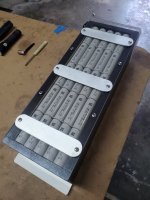
Hi Barncat, Can you post a photo of the 3/4" braided copper strap installed, making contact with the 5 cells?
 
Chipping away at it... The copper straps are ready. Various buss plates done. The aluminum angle was custom cut from rectangular tube and serves as a conductor plus stiffener for the end plate- the 1/2" polyethylene will bow slightly otherwise. Making custom copper screws from some nails available on Amazon. Very tedious but ultimately worth it.
 

Attachments

  • 20250224_170404.jpg
    20250224_170404.jpg
    6.9 MB · Views: 7
Back
Top