The care and feeding of a123-based packs...

hi gary
thats the route I'm going, twin 36v ping BMS to charge and a single LVC for discharge.
looks like I'm just waiting for the parts to come now so I will bid this thread goodbye for now.
when the pack starts to take shape I'll start a thread and post a link here or if I need any help I may be back as well.

Geoff
 
Howdy,

Just started looking into ebikes about a week ago and slowly catching up on the scene :) (so plz forgive me, im still learning lol)

Iv alot of reading to do befor i decide on a hub but stumbled into here while reading about batteries.

I have afew high end flashlights and thought i would share this link with you to AW's 18650's he has unprotected cells for $6 along with protected cells for $12 which are highly regarded in the candlepower forum for use with cree x5 and other high draw insane torches. http://www.cpfmarketplace.com/mp/showthread.php?t=184670 (you might need to go to last post to find links to the latest thread, this is the 7th part atm o_O)

Are these the same a123 batterys everyone is talking about? If not would they still be decent enough for building packs as i cant get the delware packs over in AUS for less then 3 arms and a leg :(

Would u be able to use the protected ones in packs? as the undervolt protection built into the battery would be a nice last resort and they can still output 5A befor they cut out

He also had some C size batteryies http://www.cpfmarketplace.com/mp/showthread.php?t=169872 but they are out of stock atm :(
 
Hi,

Is there a way, or what is the best way to check the condition of the cells (determine roughly the number of good cells) in bad Dewalt packs without opening them up and checking the individual cells?

There isn't any mention of how to separate the packs into individual cells. Can the metal tabs be easily removed without damaging the cells? If so how?

If not the tabs would need to be cut. What is the easiest way to do that? If the tabs are cut can packs be assembled using these cells by welding the cells together using new tabs on top of the old tabs?

GGoodrum said:
Anyway, I have not seen any real loss of capacity in any of my a123 cells, even for most of the early "abused" ones, except for the ones that got overdischarged on my bikes. For the latter ones, I've found that cells that had resting voltages that were still above about 2.5V would recover fully, with no apparent loss in capacity. Cells that got even a little below 2V, however, all seemed to immediately lose about 10% of their capacity, and have reduced "C" ratings as well, because they will have larger voltage sags, under load. An easy way to tell if an a123 cell has this reduced capacity is by checking the resting voltage about a half-hour after charging. Healthy cells will be able to hold the surface charge voltage up over 3.60V almost indefinitely, but "stressed" cells will bleed this off down to the 3.38-3.45V range within minutes.
-- Gary

Can the reduced capacity cells be used with good cells to build a pack? If so what is this best way to use them and what is the effect on the whole pack? Does a CBA II battery analyzer give more information than the above test of resting voltage?

GGoodrum said:
I'm working on a new way to build a123 packs, similar to the "stick" construction method, but not necessarily in a stick format. I'm using the same G10 plates, with nickel-plated springs for contact to the cell terminals. Each plate has four springs, with screws protruding up through the plate. Two of these plates are used with 4-cell clusters. The two plates and the four cells are bolted together, using a threaded spacer, and what you end up with is a block of four cells with "studs", for each contact.

These 4-cell blocks can be oriented, and wired, in a variety of ways. For instance, I am building an 8s6p configured pack that I will use as "booster" pack for my Townie. The blocks are oriented in a 2 x 6 configuration, hot-glued together. I'm using copper strapping (available at Lowes and Home Depot...) to connect the cells. This pack will get an 8-channel version of the new BMS board.
-- Gary

Those look nice. I gather you were not satisfied with the stick packs. Are you pretty confident these will be an improvement? Do you have ballpark idea of the price?

Are there any solderless methods for using the M1 cells in parallel groups other than Gary's packs and welding tabs?

Are there any complete explanations/diagrams for balancing/lvc/cell-charging wiring available (where)?

Thanks!

Mitch
 
MitchJi said:
Is there a way, or what is the best way to check the condition of the cells (determine roughly the number of good cells) in bad Dewalt packs without opening them up and checking the individual cells?

Hey Mitch. Have you checked with a DeWalt tool center to see if they have a battery pack analyzer? Milwaukee uses them and I've seen them in action and they are very cool. Tells individual cell voltages, # of charges, max temps and other diagnostic stuff and just slides onto the battery packs without opening them. I'd be surprised if DeWalt didn't have a similar thing.

MitchJi said:
Can the metal tabs be easily removed without damaging the cells? If so how? If not the tabs would need to be cut.

You can use needle nose pliers and "roll" the tabs off of the spot weld points without hurting the cells. Easiest tab separation tool is a dremel, which also is handy for roughing up a cell top for solder and/or grinding down the spot weld leftovers. Dremel is a pack builders best friend!

MitchJi said:
Can the reduced capacity cells be used with good cells to build a pack? If so what is this best way to use them and what is the effect on the whole pack? Does a CBA II battery analyzer give more information than the above test of resting voltage?

If you have lower capacity cells mixed with higher capacity cells the higher ones will be "pulled down" to the lower ones. Best to match the best you can, which is why...

CBA II is awesome for testing internal resistance and overall capacity. A "must have". They are kind flaky though so be careful. It's easy to blow the mosfets in them if they aren't properly tightened. They are a little off in their voltage reading too because of the way they are built. Search DocBass threads about that. Terrible customer service in my opinion.. all emails I've sent go un-answered.
 
MitchJi said:
Can the reduced capacity cells be used with good cells to build a pack? If so what is this best way to use them and what is the effect on the whole pack? Does a CBA II battery analyzer give more information than the above test of resting voltage?

If you have lower capacity cells mixed with higher capacity cells the higher ones will be "pulled down" to the lower ones. Best to match the best you can, which is why...

is that only if the reduced capacity is caused by age (mixing old and new cells)?

or does it happen with mixing different ah cells that are new (mixing 18650 with a123 with 40138 (lifebatt,bmi,psi) with headway)?
 
Im trying a different approach to the "boost pack" deal, running a 24s 10ah large 38mm cell pack (Headways)with a BMS. Unfortunately i need more than 50-60a for bursts, but dont need any more range, weight and lost space that another 24 cells would take up, so I have some a123 and thinking about putting them in a spring stick pack with out a bms in the fork just like Knuckles did. To keep the a123 from a DOD that gets them out of wack (and kills the occasional cell, i am going to run 22 cells and run them without any diodes but charge separately of course and the only time they will be parallel will be when the motor is pulling hard(Just going to trip a largeish relay or pair of 40a relays). If the large pack and the A123 are paralleled and pulled down hard, the bms on the large pack will keep the Headway cells even and when the V gets too low I will depend on a programmable controller that will LVC and shut the draw down before the a123 get below 2.4, so a periodic check of the A123 pulling them out of the tubes should be fine and I get the current delivery on peaks that i need without any space and much weight. Plus the most potential differential I can have is about .3 per cell so that just gets the a123 up to hot charge voltage anyway of 3.7 or so. Even if they are paralleled without load there will be no foul. I may play around with 23 a123 but i think 22 will be the sweet spot. 12.2ah at 80ish vdc with a 140a peaks no problem at all. Well anyway thats the theory, I let you know how it works, but i dont see how the a123 could ever feel stress. Oh and FYI- running a two speed X5 motor and Kelly controller.
 
hmmmm two speed X5 :twisted:

Doc
 
I'm trying a different approach to the "boost pack" deal, running a 24s 10ah large 38mm cell pack (Headways)with a BMS. Unfortunately i need more than 50-60a for bursts, but dont need any more range, weight and lost space that another 24 cells would take up, so I have some a123 and thinking about putting them in a spring stick pack with out a bms in the fork just like Knuckles did. To keep the a123 from a DOD that gets them out of wack (and kills the occasional cell, i am going to run 22 cells and run them without any diodes but charge separately of course and the only time they will be parallel will be when the motor is pulling hard(Just going to trip a largeish relay or pair of 40a relays).

To simplify your setup - Couldn't you just directly tie 24 A123's cell by cell in parallel with your 24 10AH Headway cells? If your Headway pack BMS does not provide the short term high current you need, just bypass the BMS controlled output, and use an LVC (possibly the output of your Headway BMS) to control the always high current capable output, as you planned to do anyway.

This way, the parallel high Amp-Hour, but higher impedance, Headway cells will continuously recharge the lower impedance A123's, while the A123's handle your short term high current needs. Also - No need to separate the two sets of cells during charging - just use the charger with your Headway BMS system and charge and balance them in parallel.

Brian
 
I finally figured out a better way to build some a123-based packs. My old method, which created 4s4p "stick"-packs, worked okay, and was easily to configure multiple "sticks" into 12s, 16s and even 24s configurations, but the problem is that in almost every one of my configurations, I really need more than 4p/9.6 Ah. What I really need for most setups is 5p, or 11.5Ah.

What I came up with is to use a similar "stacked" construction method, but this time I'm making use of the plastic end caps that are used in the DeWalt packs. Instead of having ten cells wired in series, like they are in the DeWalt packs, the cells will be organized as two sets of 5 paralleled cells each. I stripped out the existing wire springs, and instead have two 3/4" x 5" copper straps, with five battery springs attached to each strip. Four of these 10-cell packs are then "stacked", and bolted together. That makes a solid 8s5p 24V/11.5Ah sub-pack. I then plan to use two of these, one on top of the other, to end up with a 16s5p, which is exactly what I need. I just started putting these together, but I will post some pictures as soon as I finish.

The other issue I have is that I don't have a good way of sealing these packs from the elements, with a full BMS installed. I can, however, make things pretty well water-resistant, if I just use a LVC board with the pack. What I decided to do was go back to an earlier concept I had where I split the BMS into its two pieces, the LVC board, and the rest as a CMS (Charger Management System. I started down this path with the BMS that Bob and I were doing, early last year, but then abandoned it when I just couldn't deal with the heat issues. Here's what the CMS looked like:

16-Cell%20CMS-03.jpg


16-Cell%20CMS-05.jpg


I've done two new board layouts, one for the LVC, which will bolt onto the front of the 16s5p pack, and the CMS, which will mount in the same size box as above:

16-Cell%20LVC%20v3.0.jpg


16-Cell%20CMS%20v3.0.jpg


The LVC includes active cutoff, although I haven't decided whether or not to use that, or go the controller ebrake route. I'm leaning towards doing the active cutoff for these, as it will eliminate two more wires that I won't need to run to where the controller is mounted.

I've ordered the boards, and I already have the parts, so I'm hoping it won't take too long to get this going. I'll post some more pics as I make some progress.

-- Gary
 
That is just great Gary, i did not followed everything but with just what i read now it would be exactly what i would like to have just the lvc with the active cut off, i am going to use the black plastic endsfrom the dewalt pack too and i am using some rca plugs to balance them with the voltpheaks charger , but i was afraid to go low voltage ...i hope you will make some available
 
slayer said:
That is just great Gary, i did not followed everything but with just what i read now it would be exactly what i would like to have just the lvc with the active cut off, i am going to use the black plastic endsfrom the dewalt pack too and i am using some rca plugs to balance them with the voltpheaks charger , but i was afraid to go low voltage ...i hope you will make some available

Yes, I will make some available. I might do complete LVC boards, but kits at least. For the CMS, it will probably just be the boards, and a BOM for all the parts/box/etc., like I'm doing with the full BMS.

I finally scored some extra-wide pvc shrink tubing today. It is 245mm wide and just fits over two of these 8s5p packs, Anyway, if anybody needs any let me know. I had to buy a 653 foot long roll, :shock: :)

-- Gary
 
Hey Gary

Keep up the great work! I'm looking forward to seeing the lastest board, Can't wait to get these boards on my a123 packs :)

-steveo
 
That's what I am looking for a lvc with the active cut off, because I don't use a controller like these ones for E-bikes.
Gary is it possible to post a pic of the shematic, because I would try to make a layout for 4 cells 8 cells ...?
 
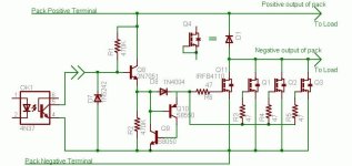
This was designed by Randomly. I have not tested it, but see no reason why it won't work.
The number/size of the FETs depends on your maximum current requirement and heat sink size.
Opto Cutoff.jpg
 
Here's a layout I did for an active cutoff LVC board for up to 24 channels:

24-Cell%20LiFePO4%20LVC-v2.3a-PCB.png


I never had much demand for this, so I never actually had any of these made. For my own use, the dedicated 16-channel version, with the board-mounted 18-pin connector is a better fit.

-- Gary
 
gary wrote: Here's a layout I did for an active cutoff LVC board for up to 24 channels:
As I intend to do layouts for 4 cells, 8 cells and maybe 12 cells with active cutoff, it would be fine to me to know the values and a better assembling print (BOM?) of your layout. The circuit design of Randomly is it the same you used?
 
manfred59 said:
As I intend to do layouts for 4 cells, 8 cells and maybe 12 cells with active cutoff, it would be fine to me to know the values and a better assembling print (BOM?) of your layout. The circuit design of Randomly is it the same you used?

I'm using the active cutoff portion of Randomly's cicuit, with the basic LVC circut that I originally did with Bob Mcree. Here is the schematic:

LiFePO4LVC-v3.1.gif


Here is a closeup of the layout, and a shot of the new 16-channel board I made for my 16s5p a123 packs:

24-Cell%20LiFePO4%20LVC-v2.3b-PCB.png


16-Cell%20LVC-v3.1-PCB.png
 
I made some more progress on my new 16s5p a123 pack yesterday. This configuration makes use of the two plastic end caps in the 10-cell DeWalt packs to hold the cells. Each five cells are connected together in parallel using 3/4" copper strapping that I get from Lowes, plus some nckel-plated battery springs from Mouser.

a123-16s5p-v3-06.jpg


a123-16s5p-v3-07.jpg


a123-16s5p-v3-02.jpg


Each 8s5p sub-block consists of four 10-cell blocks that are held together via two 6-32 threaded rods.

a123-16s5p-v3-03.jpg


a123-16s5p-v3-04.jpg


The two 8s5p sub-packs stack one on top of the other and then the 16-cell LVC board bolts to the front of the completed pack.The whole pack then will be shrink-wrapped.

a123-16s5p-v3-05.jpg


a123-16s5p-v3-01.jpg


Today I will finish up the second 8s5p sub-pack and wire up the LVC board.

-- Gary
 
WOW,
I am so very impressed, you work so fast it is just unbelievable.

this is just perfect i can t ask any better.

I want a kit like that :D
 
slayer said:
WOW,
I am so very impressed, you work so fast it is just unbelievable.

this is just perfect i can t ask any better.

I want a kit like that :D

I don't know about fast, as I've been thinking about this for awhile. Once I more or less had it sorted out in my head, putting it together has gone pretty quick. I've got lots of these end plates, leftover from a bunch of empty DeWalt cases. I've been using the strapping tape, and the battery springs in the previous "stick" packs that I did. The LVC board layout took a bit of time, but even there I kinda had an idea in my head of how it needed to be laid out.

I'm working on instructions, as I go, so I'm hoping to do a basic kit that will supply everything but the end plates and the cells, both of which you get out of the DeWalt packs.

My biggest problem is that I don't get enough time to do anything but work on it in spurts. Yesterday I wasn't able to finish the second sub-pack, as my wife had other ideas about how I was going to spend my Sunday. :roll:

-- Gary
 
Hi Gary,

GGoodrum said:
Once I more or less had it sorted out in my head, putting it together has gone pretty quick. I've got lots of these end plates, leftover from a bunch of empty DeWalt cases. I've been using the strapping tape, and the battery springs in the previous "stick" packs that I did.

If the connections are reliable (it looks like they are) this is a great idea. It looks like the actual assembly is quick and easy. The end plates simplify the process a little bit but simple plastic channels would work almost as well. This would allow the same basic method to be used in larger configurations than 5p and with different cell types (Konion for example).

With the end plates does hot glueing the cells together make assembly much easier or is that an unnecessary step?

GGoodrum said:
Each five cells are connected together in parallel using 3/4" copper strapping that I get from Lowes, plus some nckel-plated battery springs from Mouser.
Does each strap connect to five cells or to ten cells (it looks like the straps might be between the plastic caps with each end of the double springs on a different cell)? If each strap connects to 5 cells it might be a little better if the springs were fastened to the plastic end caps and you used braided copper (more flexible) straps with the springs pressing the braided copper directly onto the cells. I think this might be a little easier to assemble and remove a possible point of failure (the connection between the springs and the copper).

GGoodrum said:
I'm working on instructions, as I go, so I'm hoping to do a basic kit that will supply everything but the end plates and the cells, both of which you get out of the DeWalt packs.

-- Gary

Instructions would be great. I don't fully understand pack wiring and would really appreciate any further instructions or information.
 
MitchJi said:
If the connections are reliable (it looks like they are) this is a great idea. It looks like the actual assembly is quick and easy. The end plates simplify the process a little bit but simple plastic channels would work almost as well. This would allow the same basic method to be used in larger configurations than 5p and with different cell types (Konion for example).

With the end plates does hot glueing the cells together make assembly much easier or is that an unnecessary step?

Definitely makes assembly easier. What I do is just use the hot glue to hold 5 cells together. Also, since spacing is tight, when using the endplates, you have to not get glue between the cells. What I do is line up the five cells, put a bead on top of the "junctions", turn the cells over and do the same for the other side. Then you can install each 5-cell "half" into the endplate.

The connections are solid. I used this same method of using the copper strapping and battery springs with the 4p "stick" packs, and I used to pull 80-90A out of those all the time.

MitchJi said:
Does each strap connect to five cells or to ten cells (it looks like the straps might be between the plastic caps with each end of the double springs on a different cell)? If each strap connects to 5 cells it might be a little better if the springs were fastened to the plastic end caps and you used braided copper (more flexible) straps with the springs pressing the braided copper directly onto the cells. I think this might be a little easier to assemble and remove a possible point of failure (the connection between the springs and the copper).

Each strap connects 5 cells in parallel. In each 10-cell "block", the 5-cell blocks are opposite to one another. The last endplate connects the two 5-cell blocks in series, but in the middle sections, the 5-cell blocks are independent. This way, on the end that has the LVC board, The bottom row of cells is the pack negative connection and the top row is the pack positive connection.

For the middle endplate sections, two endplates are bolted together, with the two copper straps sandwiched in between. Two springs are bolted together with the strap in the middle. Once the two 5-cell blocks are pressed into place, the next assembly of back-to-back endplates are slid onto the two 6-32 threaded rods, and pressed on top of the cells. Then, two 6-32 nuts are put on and tightened down, which compresses the endplates, springs, and cells together. The compressed springs make very good contact with the cells, and provide a lot more surface area to conduct current than the 4 tack welds used with the tabs. Like I said, I've run 80-90A through a 4p setup like this, and nothing got warm.

MitchJi said:
Instructions would be great. I don't fully understand pack wiring and would really appreciate any further instructions or information.

I'm working on this, but it won't be before next weekend, at the earliest. In any case, I'll post some more pics as I make some more progress.

-- Gary
 
Very nice setup, like always Gary. What size battery springs are those?
 
Back
Top