
gensem
100 kW
subscribed ")


Thud said:Hey G,
from a quick glance, I think your 15t sprocket is very tight to make it fit that lovejoy..need to reveiw.
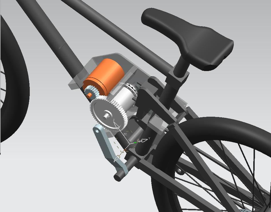
I would vote for the 2.25/2.5 tube with the steel stem.
you were getting one of Farfles extended swing arms?
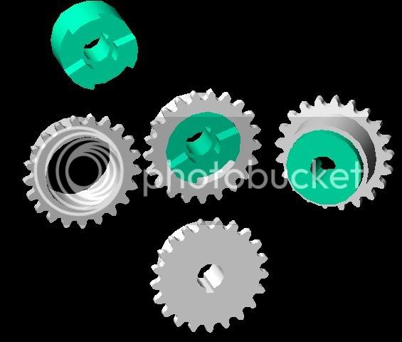
GITech said:Could you open an 18T #35 type-A sprocket to 1.75" ID?
Only thing about this idea that concerns me is it may take up more room and I don't have much to spare. With the windows cut right into the face of a type-B sprocket I figured I only would have about 1/8" of space for the lovejoy to clear the sprocket when not engaged. Maybe for this second idea I could get away with welding the type-A sprocket right out on the couplings dogs so that their tips are flush with the face of the sprocket?
Oh, or, instead of buying a type-A sprocket...just boring out the type-B sprocket already ordered to 1.75" if there is enough material on its' hub?
Thanks,
Jay
 We could explore different ways to design it here in this thread (or through PM if you wanna keep it secret, hehe). I did'nt read all of the posts because it's late again.
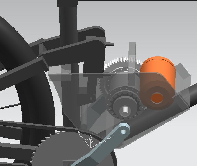
Hi crossbreak,crossbreak said:I can recommend you taking the DELTA wireing because you have to change nothing but the end-leads! You can get 75KV this way pretty easy
Lebowski said:ok, the clue is to connect everything in a triangle.
Take one winding (lets call this one 1), this is your reference. Spin motor (drill press ?) and measure AC voltage accross this
winding using normal multimeter (in the AC setting !!!!).
Take another winding (2 ?) and connect it to the first one in series. Measure the total series AC voltage. I know it sounds a bit
strange but the total series AC voltage should be equal to the AC voltage of a single winding. If you measure around 1.7 times the
voltage of a single winding then reverse the connections of winding 2 to end up with an AC voltage equal to that of a single winding.
Now connect the third winding (3) in series with 1 and 2 and measure the AC voltage again. If you measure 2 times the voltage
of a single winding, reverse the connections of winding 3. If the total AC voltage of the three series connected windings is 0 then
you've connected everything in the correct order. You can now short the start of winding 1 with the end of winding 3 (remember,
the voltage was 0 so this is no problem).
Now you got your 3 windings connected in delta.
crossbreak said:Uups . Yes of course from Delta to Y.
First you have to seperate the 6 coil leads, each two are soldered together so you get your 3 phases. Then find out their polarity. Then connect them in the wye config by soldering 3 of them together to a star point.
this is how Lebowski does it for Delta:
Lebowski said:ok, the clue is to connect everything in a triangle.
Take one winding (lets call this one 1), this is your reference. Spin motor (drill press ?) and measure AC voltage accross this
winding using normal multimeter (in the AC setting !!!!).
Take another winding (2 ?) and connect it to the first one in series. Measure the total series AC voltage. I know it sounds a bit
strange but the total series AC voltage should be equal to the AC voltage of a single winding. If you measure around 1.7 times the
voltage of a single winding then reverse the connections of winding 2 to end up with an AC voltage equal to that of a single winding.
Now connect the third winding (3) in series with 1 and 2 and measure the AC voltage again. If you measure 2 times the voltage
of a single winding, reverse the connections of winding 3. If the total AC voltage of the three series connected windings is 0 then
you've connected everything in the correct order. You can now short the start of winding 1 with the end of winding 3 (remember,
the voltage was 0 so this is no problem).
Now you got your 3 windings connected in delta.
sn0wchyld said:so to get to wye you take the 3 (lets say negative) leads that you've found by doing the above and solder them together, and take the 3 remaining 'positive' leads as your 3 phase wires?