• Hello ES! We could use some help to get us past the finish line on building the new knowledgebase for the forum.
    Can you donate? Please see our fundraising page. Thank you!

"The Mule" calls for your help to speed up Phaserunner setup with hub rear motor with unknown characteristics

aigoual

New here
Joined
Dec 18, 2025
Messages
19
Location
France
Hi everyone !

I recently purchased a second-hand Phaserunner v6 (L10) + Cycleanalyst and I am in the process of upgrading "The Mule" - a HEAVY frontload cargo bike - mostly in hope to improve its performances (peak mechanical power especially critical right now, hopefully improved through much greater efficiency) and functionality (especially electric breaking and regen).

This vehicle is mostly used in and around Cévennes (moutaineous range in France) : for commuting to the nearby city (40mn drive, and a challenging 400+ 6-8% ascent when cycling back fully loaded with two kids and a week's supply of groceries ...) and locally, for some beekeeping operations.

Currently, it is powered by a CSC rear wheel hub motor with unknown characteristics and driven by an equally unknown but particularly large Chinese controller (by chinese controller standards, and because it has let 2kw through for several rather extended periods of time, when CSC replied to me that they don't do controllers over 1.5 kW ...).

Yesterday, I managed to get the wheel spinning with the autotune feature but I already have two questions :

[1] is it possible that the autotune gets the motor to spin with wrong KV and pole pair settings ? How can I know if the motor is being driven (non-)optimally ?

[2] altough I have been very cautious with wiring, the autotune process concludes "No valid Hall signals. Maybe the hall cable is disconnected." No information in the "Detected Hall Pattern" table. Besides hardware failure and wiring error (which I will be checking next), what may be the cause of such a diagnosis ?

Any methodological advice on how to proceed promptly towards an efficient and reliable setup would also be greatly appreciated.

I will be posting my progress and new questions as I progressively solve my issues step-by-step.

Thanks in advance for any help that you may provide so that "The Mule" can be back on the road as soon as possible ! :)

Ben
 
Last edited:
You can get an inexpensive motor tester to check the hall sensors and phase wires.

Motor Tester

I recently had an issue with a GMAC motor. I tried to run autotune on it and it came back with invalid hall sensor configuration. I emailed Grin and they replied "The autotune doesn't work when you load the v6 file because of the autostart injection current being too high I believe which interferes with the autotune." I set it up with the default parameters for the GMAC in the software and the motor worked fine after that.
 
Hello RunForTheHills,

Thank you for your reply.

I took time to re-check the wiring using a different method and re-did all the soldering.
The autotune process went through and all my Hall sensors are now detected ! I am not sure what went wrong initially ... (As none of the halls were working, I assume that the 5V circuit was somehow cut).

I've emailed GrinTech a few hours ago to ask them to have a look at this thread to get a reply about my first question.

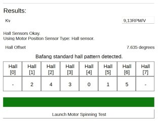
As a basis of the next steps of the setup process, I paste below the output of the autotune :
Kv = 9,13 RPM/V
Hall offset = 7,635
Number of pole pairs = 23
Rs = 76,0mOhms
Ls = 182,0uH

I've attached a screen capture of the hall pattern.

The reference I have about the hub motor (engraved on the cover) is CSC KS-W01-2104-2690
 

Attachments

  • Autotune_output.jpg
    Autotune_output.jpg
    85.4 KB · Views: 2
Hi again everyone,

As I've solved issue [2] and as the motor is spinning with Hall sensors, I'm moving on with the setup.

As I explained in my initial post, my current primary limitation is mechanical power to return home, which requires lifting 150/200kg up 400+meters on a 6-8% slope.

The display of the chinese controller previously setup was annoncing a massive 2kW of electric consumption plus serious pedalling for a max ascent speed of 15km/h , but this amount of power melted battery connectors (at the interface between the baseplate and the battery).

I intentionally pushed the setup to such limits only once before dealing with this problem :
  • I installed a chinese dual battery discharge converter (feedback on this system would be appreciated if there are users reading this, especially regarding safety) in an attempt to divide the currents by two (at battery level) by running two batteries during ascents. I have yet to test this, I will be giving feedback here.
  • Upstream the batteries, anticipating max Phaserunner current of 90A, I have thicker cables and connectors ...
BUT ... the second-hand Phaserunner I could find is an L10 ...

So I would appreciate any feedback on the software (not to damage the phaserunner or the L1019 connector ...) or hardware (heatsinks ? hack of the Phaserunner L10 to change for a connector that would allow to actually push 90A of current safely through ?).

Grin Europe (in France) wrote to me that the L1019 connector is given for 45a DC max phase current, and advised to place the connector in the air flux to cool it down ... So I am planning to start safely with a 40a software motor limit ...
 
Last edited:
Okay, the controller is all setup with some basic or default parameters. Looking forward to the first ride, as soon as I've tied everything up more or less neatly ...

Can someone please define the motor current ? This is the phase current circulating through each motor phase wires (each dephased by 120 degrees ?), right ? The software suite gives a figure, but it's a DC current, isn't it ? It would be helpful to estimate a safe DC equivalent.
 
The software suite gives a figure, but it's a DC current, isn't it ?
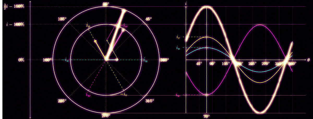
The motor current is a mathematical value coming from the FOC theory. You can calculate it from two measured phase currents (sum of the three phase currents is always zero, so you can calculate the third), with the Clarke and Park transformation.

ClarkePark_Animation
 
Last edited:
Thank you Stancecoke !

You imply "motor current" = phase current amplitude ?

What I get from your graphs is that phase currents are sine waves, so their RMS value is lower by a factor /square root of two/, and also possibly the AC current produces much less heat.

What is the max current I can push through safely, is my fundamental question ... I forgot to mention that I am currently based on 48V li-on batteries.

Regarding hardware, is the 45A limit given for the L1019 CUSMADE connectors a peak or continuous value ? What is a safe continuous value used by people who are using Phaserunners L10 ?
 
Generally an autotune will do a good job of detecting a motor. In rare cases you may need to adjust the figures, but as is usually works well.
The rest is up to you.

What is the max current I can push through safely, is my fundamental question ... I forgot to mention that I am currently based on 48V li-on batteries.

This depends on the heat you feel from the motor :)

If you don't have a temp sensor then you can assess this by hand if you can find the hottest part of the motor.
At 90C you cannot put your hand on something for multiple seconds because it is too hot.
90C on the case may mean 120C inside, which is in the danger zone.
So can't rest your hand on it = too hot = dial the power way back.

With no picture of your motor.. start a 10A batt / 25A phase

Please check this article for some helpful info on motor controller terminology:
Knowledgebase

Phaserunner has a very helpful manual. It's a good controller for someone who is just learning things.
 
Hi Neptronix and thank you !

Can I assume from your post, and from Grin's tutorials on youtube, that if the motor spins and does not make weird noises, then pole pairs and Kv settings are ok for driving the motor optimally ?

Regarding temperature, I assume there's no sensor in my motor.

I am planning to add one on the current motor at a later stage, if I can get enough torque to climb my way back. On the other hand, if the current motor is not sufficient, I will move for a more powerful motor with temperature sensor and integrated torque arm (for safety reasons due to the intensive use of electric breaking).

So yeah, lacking a good theoretical understanding of the limits of my current hardware, I was planning to go empirically, step by step, and to "sense manually" by touching the connectors, the controller. But I suppose some key limits can be derived from the hardware itself, especially max currents ?

Why do you recommend 10A max battery currents and 25A phase (in the test I did to the extent of melting battery connectors, I was drawing 2kW of electric power from the batteries, which I know is not advisable, but gives a much higher battery current than 10A) ? Is it safe to use a 2.5 ratio between DC battery output and AC phase current flow ?

Thanks for the link towards this very interesting knowledgebase that was unknown to me.

I will look deeper into that hopefully tomorrow, and add a picture of the motor to this thread.

Once again, many thanks to all of you who have already, in a single day, contributed to improve my understanding !

What an awesome community !!!
 
Last edited:
Hi Neptronix and thank you !

Can I assume from your post, and from Grin's tutorials on youtube, that if the motor spins and does not make weird noises, then I can assume the pole pairs and Kv are ok for driving the motor optimally ?

For the most part. The only thing to look out for is unusually high heat or power consumption. That is a symptom of a mostly right, but not exactly right combination.

Why do you recommend 10A max battery currents and 25A phase (in the test I did to the extent of melting battery connectors, I was drawing 2kW of electric power from them, which I know is not advisable, but gives a much higher current than 10A) ? Is it safe to use a 2.5 ratio between DC battery output and AC phase current flow ?

I recommend this because we know nothing about the motor and that 's going to come out to something like 400-600w.
If you were pushing 2kw before then i imagine you have a much bigger motor.
1:2.5 ratio is close to the default battery to phase amp ratio for most controllers.
These are just safe defaults in the case you were about to tell me you had a small geared motor.

Thanks for the link towards this very interesting knowledgebase that was unknown to me.
I will look into that hopefully tomorrow, and add a picture of the motor to this thread.

Check this article also for a primer to tuning:
Knowledgebase
 
Thanks Neptronix.

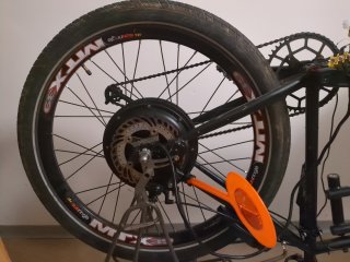
I've attached a picture of the engine. Let me know if any other photo detail can be useful.

The motor's casing is roughly 220mm in diameter, and 65mm in thickness (external dimensions).

It has also just been statorade-injected.

The picture also features a small torque arm. I am in the process of thinking through a much stronger DIY clamping torque arm that would replace the bolt on the left side. I've browsed the relevant pages on the forum, that gave me several ideas, but specific suggestions from people experienced in the 2kW range are welcome.
 

Attachments

  • IMG_20260213_220751_996.jpg
    IMG_20260213_220751_996.jpg
    7.2 MB · Views: 8
Looks like ya typical 9C clone.
Consider an ebikes.ca clamping torque arm if the task of making your own is too hard.
It would be very hard to do a better job.
..and then put the current weak-ish torque arm on the other side.

40A batt / 100A phase is a nice place to start for a 9C clone. But watch the heat :)
 
Hi Neptronix, thank you !

I was suspecting it might be a RH212 clone. I've read somewhere there are two versions, and I'm hoping it's a torquey slow winding. Does that make sense ? It would be a nice confirmation, as this was the low-budget option with best performances given my needs, based on Grin's simulator. Any way I can identify/confirm the specific model it has been cloned from ?

Regarding GrinTech's torque arm, I've considered it but I am on a very low budget atm and this build may only be a prototype or an earlier version of an improved cargo bike, as I have some concerns with the frame (mostly functional, possibly structural).

Also, if I upgrade the motor, I will preferably go for one with an integrated torque arm (currently waiting for Heinzmann or Grin second hand motor opportunities).

I would invest in Grin's torque arm right away if it could be transplanted (as a redundancy, for moving it to another motor or frame, for selling if I end up not needing it) but that is not the case in their design.

And I prefer, as much as possible, rigging solutions that could be fixed in case of failure in places where there are only basic tools.
 
Hi everyone,

I've made good progress and I will be making the first trials in one or two days if the weather allows.

I've got two wiring questions regarding the broader integration of the CA and the PhaseRunner :
- I've made my tests using this ebikes.ca thumb throttle (similar to this one) that came with the controller, but was hoping to keep my twist throttle (a basic generic chinese one). I've tried to wire it but I can't get it to work. Is there something special I need to know ?
- I would like to wire my brake light. I've read somewhere that it is possible with the CA or the Phaserunner, but that it requires some simple components inbetween. Can someone explain me how to do that ?

Regarding the currents, can I already substantially increase them ? What is the advantage of starting with such low currents ?

Many thanks !
 
Regarding the design of my controls, my idea is to have back-pedaling regen, and I want to keep my current twist throttle because it is discreet and because it works more or less well besides basic ergonomic handles. I am considering Grin's two-ways twist throttle as a redundancy but it does not seem sufficiently mature yet (works only with alpha CA software).
 
I would invest in Grin's torque arm right away if it could be transplanted (as a redundancy, for moving it to another motor or frame, for selling if I end up not needing it) but that is not the case in their design.
The TA is entirely portable, and trivial to uninstall it and transplant it to another motor, frame, or bike.

And I prefer, as much as possible, rigging solutions that could be fixed in case of failure in places where there are only basic tools.
The Grin clamping TAs are installed and adjusted with common basic hand tools common to basic bicycle assembly and maintenance.
 
Hi Neptronix, thank you !

I was suspecting it might be a RH212 clone. I've read somewhere there are two versions, and I'm hoping it's a torquey slow winding. Does that make sense ? It would be a nice confirmation, as this was the low-budget option with best performances given my needs, based on Grin's simulator. Any way I can identify/confirm the specific model it has been cloned from ?

Not without taking it apart and showing it's guts. If you have a programmable controller, it might have a 'poles' setting set, that would be helpful because this motor is taller and has more poles than a typical 9C clone.

>95% of hub motors are 9C clones, and this looks a lot like one from the pictures.

Regarding GrinTech's torque arm, I've considered it but I am on a very low budget atm and this build may only be a prototype or an earlier version of an improved cargo bike, as I have some concerns with the frame (mostly functional, possibly structural).

The ~$70 part is a lot cheaper than replacing a $200-$5000 bike because the dropouts got ruined from high power. Worth every buck.
I get why you would hesitate.

Unfortunately two cheap and kind of loose torque arms ( 1mm of play is too much, if you don't have to hammer the torque arm a bit onto the axle, it's not doing a great job ) has less motor holding ability than a single one of those due to the clamping action.

I would only run them short term.

I would invest in Grin's torque arm right away if it could be transplanted (as a redundancy, for moving it to another motor or frame, for selling if I end up not needing it) but that is not the case in their design.

And I prefer, as much as possible, rigging solutions that could be fixed in case of failure in places where there are only basic tools.

That torque arm i mentioned is the easiest of grin's to get on and off a bike in the case of a popped tire etc.
If you are in an area where you get a lot of flats, it pays for itself in hassle reduction.
A motor like an all axle is a little easier.
 
Hello,

I took the bike on a short ride today and it was AWESOME. I've reached speeds I have never reached before, electric breaking works, back-pedal regen works ... Some fine-tuning to do, but it all works.

For a reason that I couldn't understand, though, I could not exceed approx 1800W of electric power.

Regarding the torque arm, I still believe it is relatively easy to build a simple diy CLAMPING torque arm. Their design is overly sophisticated and pricey for my bike. 70 euros is the price of my spare (second-hand but nearly new) hub motor !

Any idea what may be wrong regarding my twist throttle ?

Thank you !
 
Regarding the torque arm, I still believe it is relatively easy to build a simple diy CLAMPING torque arm. Their design is overly sophisticated and pricey for my bike. 70 euros is the price of my spare (second-hand but nearly new) hub motor !
Here are some examples of clamping torque arms:

I like the sliver one in the 3rd pic, simple, I am going to make one someday.

Mine is the one in the 4th pic, for that one to work, you would have to make dropout extensions.
(you can read the full build in my Catrike 700 in my sig below)
 
Thanks for those sturdy suggestions A-DamW !

What do you mean by dropout extensions ? Could you attach a picture please ?

My frame is an old design : the flat parts of the motor axle are vertical.

I'm thinking of two pieces of corner steel pinching the axle, with a third arm going to the frame.
 
What do you mean by dropout extensions ? Could you attach a picture please ?
This is one of my build threads, scroll down through the pictures and descriptions.
 
I recently installed Grin's 2-way throttle on a bike operating through a Phaserunner controller. Works great!
Thanks for the feedback. Which version of the CA software are you using please ? Do you also have back-pedal regen ?
 
Not using a CA, kit came with a Super harness and 3rd party display. So it's all done by the controller. I have a front brake switch for regen, and variable regen on the throttle.
 
Back
Top