Those motor/controller testers DO NOT Work.

Freddy1

1 mW
Joined
Sep 27, 2022
Messages
18
A post, just so it may be helpful for someone in the future......

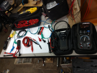
After spending MANY long hours trying to find why my new controller (KT Sine) was throwing an error (motor position sensor fault on a KT LCD8 display) when being checked with one of those relatively cheap Chinese motor/controller testers, I finally discovered it was the tester itself causing the error code.

The motor testing bit works as it should, still nothing that you can't determine with a multimeter. However, on the controller testing side, the only thing that really works is showing 5V is available at the red/black hall wires (something again easily determined with a multimeter). The controller phase and hall testing bit is flawed, continually throwing the error code.

Finally in total frustration, just connect the controller to the motor, all same colours, and it worked perfectly with no error code. It was the testing device that was causing the error code. This same error code appears when the hall wires are disconnected.

If someone is wondering why I was testing a brand new controller, nothing was working when first connected .... because dumbo hadn't pushed the juliet connector ALL the way home. Yes, I now know there is a line on it to signify when it is completely clipped in.
 
Freddy1 said:
still nothing that you can't determine with a multimeter.

I disagree. there is alot that lil machine tells you that a multimeter wont.
 
DogDipstick said:
Freddy1 said:
still nothing that you can't determine with a multimeter.

I disagree. there is alot that lil machine tells you that a multimeter wont.

Such as?

I was able to determine the motor was 100% fine by comparing the resistance of all the phase wires, and that the hall sensors worked correctly by checking the voltage of the hall wires, while putting 5Volts into the red/black lines, and rotating the wheel. As well check 'chugging' by connecting combinations of two phase wires and rotate the wheel backward (a geared motor). From those simple 3 tests I was able to have 100% confidence the motor was fine. The tester told me nothing additional.

I can check the controller is putting out 5V hall voltage (black and red wires) with a multi meter. That's all the tested does with a little light that come on. I can check the phase lines of the controller by testing the resistance of each through to the positive and negative battery inputs. The only thing my multi meter doesn't do is cause the display to show nonexistent errors like it does when the controller is connected to the tester. That thing caused me to waste countless hours trying to find a non existent problem. A piece of junk in my opinion.

The throttle and PAS are also easily checked with a multimeter using a 5V input to their respective red/black wires and checking the signal line while operating. My 5V source is nothing other than an appropriate old phone? charger with the plug cut off and a couple small alligator clips crimped on. Just found an appropriate one from the box full of old charges I've saved over the years. Always figured I find some use for them.
 
Freddy1 said:
DogDipstick said:
Freddy1 said:
still nothing that you can't determine with a multimeter.

I disagree. there is alot that lil machine tells you that a multimeter wont.

Such as?

I was able to determine the motor was 100% fine by comparing the resistance of all the phase wires, and that the hall sensors worked correctly by checking the voltage of the hall wires, while putting 5Volts into the red/black lines, and rotating the wheel. As well check 'chugging' by connecting combinations of two phase wires and rotate the wheel backward (a geared motor). From those simple 3 tests I was able to have 100% confidence the motor was fine. The tester told me nothing additional.

I can check the controller is putting out 5V hall voltage (black and red wires) with a multi meter. That's all the tested does with a little light that come on. I can check the phase lines of the controller by testing the resistance of each through to the positive and negative battery inputs. The only thing my multi meter doesn't do is cause the display to show nonexistent errors like it does when the controller is connected to the tester. That thing caused me to waste countless hours trying to find a non existent problem. A piece of junk in my opinion.

The throttle and PAS are also easily checked with a multimeter using a 5V input to their respective red/black wires and checking the signal line while operating. My 5V source is nothing other than an appropriate old phone? charger with the plug cut off and a couple small alligator clips crimped on. Just found an appropriate one from the box full of old charges I've saved over the years. Always figured I find some use for them.
Thanks for sharing. :thumb: You must have felt quite foolish for getting one. They say there's a sucker born every minute, so live and learn I guess. :cry:
 
Freddy1 said:
I was able to determine the motor was 100% fine by comparing the resistance of all the phase wires,

Motor phase resistance is so low that a typical multimeter registers it as essentially a short circuit--the meter leads can have as much resistance as the phases do. Even some better ones like the DE-5000 I have here have difficulty reading that low a resistance. There are procedures using other methods than direct resistance testing that can yield useful results, but just a direct resistance reading with a typical multimeter doesn't typically do so.

What brand and model meter, and measurement procedure, are you using to test with? Could be helpful to future readers that need to do this.
 
amberwolf said:
What brand and model meter, and measurement procedure, are you using to test with? Could be helpful to future readers that need to do this.

Looks the same as a thousand other ones posted for sale on the internet, with the only 'band' name being "Bo Ai Zhi" with "Made in China" underneath. When I checked reviews on Amazon (could have been another supplier) there were a number of people who said they didn't work, that is my experience also.
 
E-HP said:
Thanks for sharing. :thumb: You must have felt quite foolish for getting one. They say there's a sucker born every minute, so live and learn I guess. :cry:

No, not foolish for purchasing the tester, just part of the learning process and the thing was dirt cheap. I feel foolish for not pushing the juliet connector all the way home which was the initial problem of why there wasn't 5v at the hall power line.

I learned a lot in the frustrating process. There have been lots of other 'learnings' in getting this POS Chinese fat bike to work, which it now does, just got to do the final wire tidy up.
 
amberwolf said:
Freddy1 said:
I was able to determine the motor was 100% fine by comparing the resistance of all the phase wires,

Motor phase resistance is so low that a typical multimeter registers it as essentially a short circuit--the meter leads can have as mu

Dont forget the pull ups for the halls. Multimeter wont have that circuit. Noope.

Or the whole impossibility of measuring a shorted winding with a tool that wont go low on its resolutio wnuf that is connected in Delta ( and may just show you the short( s) to the next winding on your reading).


I mean jebus the Grumbler coil would have never been invented, if the multimeter, would suffice.
 
DogDipstick said:
I mean jebus the Grumbler coil would have never been invented, if the multimeter, would suffice.

Growler? If not, please explain what you're talking about.
 
Chalo said:
DogDipstick said:
I mean jeb

Growler? If not,

Google is your friend,... No?
https://www.google.com/search?q=Grumbler+coil+&client=firefox-b-1-d&sxsrf=ALiCzsZUkR47tElS5raY6Zs6nYfrLO3xag%3A1667414441537&ei=qbliY-GeIN6pptQP9-q06A0&ved=0ahUKEwihl-zrkpD7AhXelIkEHXc1Dd0Q4dUDCBA&uact=5&oq=Grumbler+coil+&gs_lcp=Cgxnd3Mtd2l6LXNlcnAQAzIFCCEQoAEyBQghEKABMgUIIRCgATIFCCEQoAEyBQghEKABMgUIIRCrAjoHCCMQsAMQJzoKCAAQRxDWBBCwAzoECCMQJ0oECEEYAEoECEYYAFDsCFi-CmD9DWgBcAF4AIABrwSIAZMHkgEHMy0xLjAuMZgBAKABAcgBCcABAQ&sclient=gws-wiz-serp
Anyway it is a very useful device. Not only for motor testing but for many many other uses such as an isolation transformer for your scope. Etc. Growler Grumbler same thing. Lol.

https://en.wikipedia.org/wiki/Growler_(electrical_device)


to test series and interpoles (commutating) fields from a DC motor
to determine phasing and polarity in multiwinding armatures
to test rotors in rotating frequency changers, as well as in wound rotors
to test shorts between turns in taped coils before installation into an armature or a stator
as a low voltage isolation transformer
as a high voltage autotransformer bucking or boosting for numerous tests on various types of equipment
for preheating or baking armatures and rotors.
 
DogDipstick said:
amberwolf said:
Freddy1 said:
I was able to determine the motor was 100% fine by comparing the resistance of all the phase wires,

Motor phase resistance is so low that a typical multimeter registers it as essentially a short circuit--the meter leads can have as mu

Dont forget the pull ups for the halls. Multimeter wont have that circuit. Noope.

Or the whole impossibility of measuring a shorted winding with a tool that wont go low on its resolutio wnuf that is connected in Delta ( and may just show you the short( s) to the next winding on your reading).


I mean jebus the Grumbler coil would have never been invented, if the multimeter, would suffice.
If I were building ebikes regularly, then I might get one, mainly because it seems like it takes three hands to take a lot of the measurements, so just being able to plug things in rather juggling leads would be my main motivation. Eliminate the chances of frying something while diagnosing an issue.
 
E-HP said:
If I were building ebikes regularly, then I might get one, mainly because it seems like it takes three hands to take a lot of the measurements, so just being able to plug things in rather juggling leads would be my main motivation. Eliminate the chances of frying something while diagnosing an issue.

The best investment for the problem you mention is no more that a cheap pack of test leads (or make them yourself). The simple bits of wire with a small alligator type clip on each end. No more mucking around trying to hold ever thing. Just clip it all up, and complete hands free to watch the meter reading, turn the wheel, whatever.

I also invested to time to make a simple julian 'splitter out' cable. The relevant julian connector short lengths of individual single wires with a more testable connection on the other. No more probing around in that difficult julian type connector.

It's so much easier when equipped with these basic 'tools'.
 
Oh yeah.

I get asked to fix alot of things. I happened to organize my pouches the other day and took a pic. My typical goto every day carry getup/setup. I got clips, extensions, alligators, fusers, needles, pierces, 3kA clamps, 10x/1x AC clamp three or four sets of spring loaded grabbers, a huge amount of Panduit silicone alligators...Datalogger, etc... Lol. hell, those two yellow Panduit piercers are 65$ alone. All Cat IV I think. They all plug into each other, and in some gang up multiples for sensing points in the circuits..... I got bags of shorting bars, banana jacks, and the like.

I like to measure shit. lol. While not worried I am gonna get hurt or blow something up. Looking at well over 2500$ in power analytics here. In this pic.
 

Attachments

  • IMG_20221106_113945777.png
    IMG_20221106_113945777.png
    961.6 KB · Views: 106
  • IMG_20221106_113951751.png
    IMG_20221106_113951751.png
    857 KB · Views: 106
  • IMG_20221106_113953172.png
    IMG_20221106_113953172.png
    887.1 KB · Views: 106
Freddy1 said:
The best investment for the problem you mention is no more that a cheap pack of test leads (or make them yourself). The simple bits of wire with a small ...

It's so much easier when equipped with these basic 'tools'.
As you were saying? equip yourself with the Julian to clip system Oh yeah I got loads of those little thingers... Helpful little diagnosis plugs for this or that circuit... to test... setup for this and that... and...

Ironically,I (also) put alligator clips and long leads on my cheapomotor tester...
muhahaha best of both worlds. Often the different motors i am testing have very diffent plugs,a nd this way i can just clip on to whatever I need to.

My next purchases are prolly gonna be an Extech Phase Rotation sequence detector. I have been looking or one for a while.

That, or a better oscilloscope.

https://www.testequipmentdepot.com/extech/electrical-testers/phase-and-motor-rotation-testers/phase-sequence-tester-displays-graphical-phase-480400.htm?ref=gbase&gclid=CjwKCAiA9qKbBhAzEiwAS4yeDeAyBA17PgEbCabe0Dow4y5UuikUxEhmobbzzBOFL7klbVygf7nxqxoCm-sQAvD_BwE
 
Back
Top