Throttle signal is higher than the supply

dawrench

1 W
Joined
Nov 22, 2012
Messages
59
Location
Ottawa Area
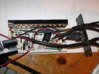
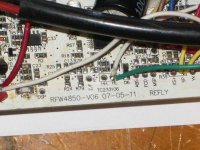
My turn to have a controller problem. 48 volt 40 amp crystalyte controller. When I opened the case, I could not see any blackened components and there was no Magic Smoke smell. On power up the external LED comes on and the on board status LED gives me 8 blinks - no throttle signal. Throttle Red to Black voltage is 4.2 while Green to Black is 4.4 volts. How can the signal be higher than the supply? Photos are of my board.
 

Attachments

  • 4840 board.jpg
    4840 board.jpg
    116.4 KB · Views: 902
  • 4840 ver.jpg
    4840 ver.jpg
    122.5 KB · Views: 902
Was that a closed or open throttle voltage? the controller will have an ignore system to prevent it taking off like a scalded cat on start up, if the throttle closed voltage is too high you will get this fault, problem could be your throttle?
 
The throttle has been tested with another controller and works fine.
 
Power On without throttle and the LED board status light does not blink. With no throttle connected, supply is 4.22v and signal is 4.24v. There is no connection between supply and signal wires. If I connect the throttle with power on, led does not change. Power on with throttle and the led blinks 8 flashes. Also when I connect the throttle, the LED dims slightly.

Using a motor I know to be good....
Power on with phases disconnected or not does not cause LED to blink.

Making the hall connector causes the LED to dim a lot.
 
All voltages specified are with the throttle closed and changing throttle position did not change output signal.
 
Without a diagram or having the controller to test its near impossible to work out what is going on. but here are some possible ideas , your voltmeter is faulty or has a low battery, there is a pull up resistor from the +5 to the signal input, there is a short from the +5 to the signal input or the mcu has popped and is outputting +5 from its input pin. Do you have any resistance between the signal input wire and the + wire ?.
 
Voltages measured used the throttle ground pad on the board. I borrowed a more expensive voltmeter and will verify the numbers with that.
 
OK, Measuring from the battery + and – lines to the motor phases I got between 8 and 10 kohms for all combinations.
No continuity between the + wire and signal input.
I unsoldered the throttle signal wire from its pad and measured the throttle voltages again.
Using a different multimeter from the first time, from the throttle ground pad on the board to the Red is 4.23 volts and from the throttle signal pad to ground is 4.24 volts.
It looks like Gwhy! Is right – the mcu is history.
I don’t have the tools or hands to repair a surface mount board. Is there someone out there that can do this? PM me.
 
Back
Top