Triangle ebike battery stopped working help :(

vega09

1 µW
Joined
Jan 28, 2024
Messages
2
Location
Budapest
TLDR: battery doesn't work but it does charge. The controller is fine (tested it with 2 different batteries)


I was riding to work the other day and all of a sudden the battery died.

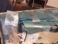
I've had this issue before where one or two of the side wires weren't soldered properly and they detached during riding (there are bumpy roads in my area). It doesn't seem to be the case now, i've triple checked.

It is a 52v48ah (custom made) with panasonic cells. I bought it about 2 years ago. The motor is bbshd.

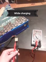
The battery still charges when connected to the charger.

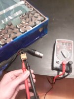
The multimeter shows no activity on the xt90 connector. However when I put it to charge it shows as if everything's ok.

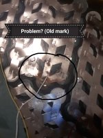
I dont know anything about batteries, is the bms broken? Or is there a broken wire somewhere? I've visually checked multiple times all the wires and they all seem ok.


TLDR: battery doesn't work but it does charge. The controller is fine (tested it with 2 different batteries)
 

Attachments

  • 20240129_044837.jpg
    20240129_044837.jpg
    2.3 MB · Views: 10
  • 20240129_044039.jpg
    20240129_044039.jpg
    1.6 MB · Views: 9
  • 20240129_044518.jpg
    20240129_044518.jpg
    690.3 KB · Views: 10
  • 20240129_043837.jpg
    20240129_043837.jpg
    2.3 MB · Views: 10
Last edited:
What are the voltages between each of the wires from the cells to the BMS, at the BMS connector?

There are probably 15 wires, and you should get 14 sets of voltages in this test.

They should all be exactly identical.

If they are more than about 0.1v different from each other, the BMS may have turned the output off to protect against a problem that can lead to a fire (if there is cell damage or defects, or aging, which is usually what causes that much difference between cells). (the input is usually also turned off in such cases, but I think I've seen at least a couple where that didn't happen..or it turned the input off but not the output).

(Sometimes a battery can also be miswired so instead of connecting to C- on the BMS, the charge negative wire is connected either directly to the cells (B- on the BMS) or to the discharge connector (P- on the BMS), for BMSes that are separate-port and should have each connector wired separately. (for common port BMS they *should* both be wired to the same point on the BMS, often called C-). If it is miswired on a separate-port BMS, then the BMS can't prevent charging even if something is wrong, so things appear to be working when they actually shouldn't be.)


There is a possibility that the balance wire that came off the cells touched a different group, and placed a voltage across that BMS sense input that damaged the BMS so it's been unable to correctly do it's job, and that group (or another) has finally reached the point the BMS turned the output off because of it.


FWIW, corrosion isn't generally a good sign. It may just indicate that humidity has affected cheap steel that was used instead of pure nickel for interconnects, which means it can corrode and that it has more resistance and so worse voltage drop under load (and more power wasted as heat inside the battery instead of driving your wheel).

But it could indicate that water has intruded into the case at some point, and could also have affected the cells. If you find that group has a different voltage than the others but all others are the same as each other, then that's a possible cause.
 
Last edited:
What are the voltages between each of the wires from the cells to the BMS, at the BMS connector?
How exactly do I do that? I unsolder the wires
from the cells and place the multimeter at the connector and at the unsoldered part?

Btw all of a sudden the battery works. Didn't do nothing to it, of course. Arghh...
 
If it suddenly works then it is probably a connection problem, most likely in the balance/sense wires (since at least one has already come off).

For testing there is no unsoldering required.

The steps below are generic because I can't clearly see the BMS connectors in your pics. If you can't touch your probes to the contacts (metal pins at the connector the wires go into), you may have to use some smaller wire or even needles attached to the meter probes to do the test.
or even file/grind/sand the meter probes you have to needle points

(there's also youtube videos on making DIY needle probes, etc).

Sometimes it's easier to unplug the connector to the BMS and test that way, but there are risks to doing that since things can get broken in the process, or wires pulled out, etc.


Be careful not to short anything together in the process.


Voltages are checked by setting the meter to 20VDC (if it's manual and not autoranging), making sure you have the black and red leads plugged into the correct holes on the meter face for this (it's instructions will show you which those are), then placing the voltmeter's black lead on the main B- battery wire, at the cells or at the BMS, and the red lead on the metal of the pin of the first of those thin wires at the BMS connector. This voltage should be one cell's worth; if it's "out of range" or a high voltage, move the red lead to the other end of the connector.

That gives you the first voltage to write down.

Move the black lead to where the red lead is, and move the red lead to the next wire over's metal pin; this is the next voltage to write down.

Repeat that step until all of the thin wires at that BMS connector have been checked and written down.

All the voltages should be positive; if any are negative make sure you always move the black lead to where the read lead is before moving the red lead, and don't "skip" a wire with the black lead. It's important because a *real* negative voltage means damaged cell groups that have been discharged so far that they got reverse charged in the process, which is not healthy for them. :(
 
I would assume that with the amount of corrosion on the cell interconnects shown in your pictures that it would make the battery NFG. If not now, soon.
 
Back
Top