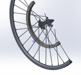
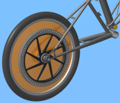
Ultimate lightweight wheel-motor concept

Deeply respectful and understood. :)

The issues for me are strength + temp, and the two vectors narrow pretty quickly on price.

To have high temp, and by that – load tolerance, you give up strength;

Magnetic Characteristics

To get best economy – you need strength, but they are susceptible to heat fatigue.

A good approach is to design where you never have to worry about heat; that the ambient temp will work in your favor when internal cooling concepts may fail.

Always pay the (conservative) piper. A robust design is better (financially when it’s your own money) than an edgy effort.

I can’t speak for your influences, but with the 150°C limit, you are topped out at N45SH. In contrast, common Chinese hubs are at the bottom rung of strength though are able to withstand a lot of heat. How many threads have been written about roasted hubs, but once the windings are replaced – they’re good to go?

It’s a tough choice.

BTW, It’s not worth getting the top-of-the-line magnets. Better to find the middle-best (owing to consistency of manufacturing) and work with that.

Don’t forget about epoxies; they – and the materials you bond to have limits and costs:
Much of Engineering is also about managing the budget of prototyping and production.

Financially, Reality of Manufacturing is a beotch. Be Prepared
…to have deep pockets. KF
 
Kingfish said:
I can’t speak for your influences, but with the 150°C limit, you are topped out at N45SH. In contrast, common Chinese hubs are at the bottom rung of strength though are able to withstand a lot of heat. How many threads have been written about roasted hubs, but once the windings are replaced – they’re good to go?
Do we know that is due to the use of high temperature magnets, though?

Given this thread is about "ultimate lightweight" and cost isn't a priority. For outrunners, high strength magnets allow you to increase the airgap radius within a given O.D. For inrunners, the only advantage is less centrifugal force on the bond to the rotor. Greater volume of lower strength material is cheaper...
 
Most mfgs are phasing out n32 now and you actually have to pay a premium over n35

In some cases

They simply dont get as many requests for it now but for legacy designs

In a few years they will be phasing out n35

They recommend using a minimum of n40 for new designs

N40 is the most popular now which is why it may be the sweetspot

Crystalyte hub motors are sh grade mags

Not sure about 9c or cromotor
 
Regarding cooling, I suspect the intention with this motor would be to produced something highly efficient. We're used to ~70% efficient hubmotors, that's why they cook. If this project could achieve something in the region of upto maybe 95% (realistic?) then overheating should be much, much less of an issue.

Regarding "wheelie-ing", that seems a tall demand for a 1Kw motor? I think it's also far too vague for a technical spec, let's stick to Nm or ft.lb :)

Am I right in saying that the goal here is a motor of modest power (at least in the initial design), with low weight being the primary concern? I.e. a motor you could put on a lightweight road racing bike and not spoil the bike? Ergo, a power/torque monster for climbing offroad mountain tracks is not what we're considering for the initial version, at least?

I'm not trying to annoy anyone, but it's good to maintain focus. Otherwise, with lots of "would be nice if it..." inputs from lots of people we end up with the new office building Dilbert had to design, or, as the saying goes, a camel, which is allegedly a horse designed by commitee ;)
 
Our initial design is for a lightweight efficient DD hub with lots of torque for a road/touring bike wheel. Idea is to come up with something that keeps a bike feeling as much a bike as possible, and still be able to deliver significant torque without gear reductions, large battery packs and controllers. Ideal would be to have a decent range commuter you could still shoulder (carry) up to your flat.
 
The only reason I mention wheelie is because in my experience a direct drive hub motor bike that cant wheelie doesnt have chance at taking you up a long steep hill without overheating. You will notice a big hub motor in a 20 inch wheel has no problem lifting the front wheel, and is also quite happy lugging up hills. Even a cromotor in a 29" wheel is not happy.

The goal here was to maximixe diameter to maximize torque, but if we go with a bionx d series motor how larger can we go? Keep it thin to keep it light. Thin means Low power (1000w contin)

The reason we want large diameter and thin is bacause for radial flux motors torque scales with the square of diameter. Double diameter and you get four times the torque. Double the width and you only get double the torque. Better to go as large diameter wise as possible before you start growing the width

The bmc gear motor starts saturating at 70nm (current saturation)

Play around with the simulator
http://www.ebikes.ca/tools/simulator.html

The problem for me is the hill to my house is over a 27% grade. The simulator only goes to 20% but you can extrapolate. Best bet is try try and get up them as fast as possible, but loaded with cargo or without a running start.... With a cold motor and a running start it is not problem to climb one steep hill, but if the motor is already hot from other hills it is really easy to smoke em. This is only one city block. Not climbing a mountain.

More here

http://endless-sphere.com/forums/viewtopic.php?f=2&t=14494
 
Hi, i watched this thread from the beginning. i very like the concept with longer spokes laced near the axle:
- no need to drill rims
- more suspension effect

I am no expert in motor technology, but i have some knowledge in construction which i learnd in a technical school a few years ago.
the past two hours i have think of how such a motor could be built (the axle, sidecovers etc).
take a look on my sketch on a piece of paper (scale is about 1:2 if 300mm stator):

dxio.jpg


i made no measurements. just a drawing to see how it will look.

improvement suggestions desirable :)

to figure out:

- how to mount side plates to magnet ring with back emf iron
- how to mount the stator laminations to the middle plate
- maybe move bearings more outwards (i think the more far away the bearings are from the chainline / brake rotor, the more stress there will be) or do you think the side plates will make it stiff and solid?
 
Yes that is basically it. I think you definitely want the stator frame to be al rather than carbon to sink heat

Carbon fiber side covers for sure

The back iron can probably be a chunk of low carbon steel

not worth Hiperco lams

Remember more lams mean more insulation (fill factor)

For a rough worst case 700cc (29") idea here is ring in a wheel

333mm diamter 18mm wide ring

700cc wheel with 100mm hub cross laced

Just makes it

Miles first sim was a 14mm stack with a 330mm rotor outer diameter but we need more with for side plates and what not

Do we want this thing to fit 24" rims or are we happy with the common 26" rim

700cc 100mm dropout 18wide 33diameter.PNG
 
JennyB said:
This may be mad, but seeing there are so many lightweight disc-brake road bikes around these days... IF the motor could be made an effective rear brake... build it as a direct replacement for a six-bolt rotor. Then you can use whatever superlight disc-compatible hub you like, and your superlightweight frame is already built to deal with the torque. :mrgreen:

Miles said:
The other possibility is to mount a motor on the cassette driver - an idea which was proposed by a certain R. Draper IIRC....

The SRAM Dual-drive could be used, if you wanted a 3-speed...........

Anybody think these ideas are worth pursuing?

A cassette driver mounted system can take advantage of the space created by the wheel dishing. It would require an additional pedal freewheel or freewheeling crank, though.

Disc brake mounted system leaves the pedal drive intact but there's less space available and, of course, you'd need a frame designed for discs.
 
flathill said:
Yes that is basically it. I think you definitely want the stator frame to be al rather than carbon to sink heat

Carbon fiber side covers for sure

The back iron can probably be a chunk of low carbon steel

not worth Hiperco lams

Remember more lams mean more insulation (fill factor)

For a rough worst case 700cc (29") idea here is ring in a wheel

333mm diamter 18mm wide ring

700cc wheel with 100mm hub cross laced

Just makes it

Miles first sim was a 14mm stack with a 330mm rotor outer diameter but we need more with for side plates and what not

Do we want this thing to fit 24" rims or are we happy with the common 26" rim

yes an Al stator frame is the better choice. Do you think this still can be a plate cut out precise of an Al sheet (water jet) or should this frame be better injected molded or cnc milled?

i think with some special rims / spoke hole design it will fit in 24" rims too - maybe even in smaller rims..
we also can move the flanges for the spokes on the hub more outwards to have more space between motor and spokes, but this would cuase less space for the cassette or wider dropouts.

if the carbon side plates must be bolted to the back emf iron ring, it has to be very thick for tape threads into it.
what about make a notch in the carbon sideplates and clamp this ring between them?
 
g5yb.jpg


all Al screws to make it lightweight
is it practial?
 
Miles said:
JennyB said:
This may be mad, but seeing there are so many lightweight disc-brake road bikes around these days... IF the motor could be made an effective rear brake... build it as a direct replacement for a six-bolt rotor. Then you can use whatever superlight disc-compatible hub you like, and your superlightweight frame is already built to deal with the torque. :mrgreen:

Miles said:
The other possibility is to mount a motor on the cassette driver - an idea which was proposed by a certain R. Draper IIRC....

The SRAM Dual-drive could be used, if you wanted a 3-speed...........

Anybody think these ideas are worth pursuing?

A cassette driver mounted system can take advantage of the space created by the wheel dishing. It would require an additional pedal freewheel or freewheeling crank, though.

Disc brake mounted system leaves the pedal drive intact but there's less space available and, of course, you'd need a frame designed for discs.

I like the cassette or brake side mount motor idea. It would leave the wheel intact if you decided to remove the motor for any repair / missing parts issues and allow you to continue riding the same machine. Even if wiring and battery compartment remain it would be a much more simple on-off. It could also confuse law enforcement efforts when times turn and you are under heightened scrutiny, you could easily just remove motor for a few weeks if need be and still ride to work without issue.
 
A potential problem there is how much space you have before fouling the chain stay. I just took a quick look at my own bike and I doubt you'd get a 400mm motor of any thin-ness in the space.

Al sheet stator frame: How much lateral stiffness is required? Will gryroscopic forces be significant and need resisting? Stiffening ribs may be required, complicating manufacture.

Clamping bolts for the side covers could work as long as they allow accurateish locating of the covers. The other option is to turn the back iron to form a channel section, giving a flange each side to tap threads through. You could make it thin and use lots of small screws (maybe M2?) or cut away sections to leave "ears" for a smaller number of larger screws (M4). I'm not sure which would be lighter, but I'd guess the latter.

You could also heat shrink aluminium hoops onto the steel flux ring to create flanges, but I'm not sure this would be lighter than the steel ears, plus it'd be a ball-ache to produce and you'd (arguably) need thread inserts for durability.

I really ought to find a copy of solidworks and do some weight comparisons...
 
A motor on cassette or brake rotor side is a nice idea, but it causes some problems: no more shifting or no rear brake. I i know a rearbrake is not absolutely necessary due to regen braking, but its a nice to have.
I think it also will not be easy and cheap to fabricate such a motor and, where would you fix the stator to? on the mounting holes for the brake piston?

@ Punx0r

gyroscopic forces will not be much due to low rpm and lightweight rotor. I think with some 3-4mm carbonfiber discs it should work without the add of complicating stiffening ribs.
Are there only radial forces in the stator, or are there also some axial forces due to magnetism? I think its not, so the stator frame mainly must be designed for torque.

turn the back emf ring like a U - shape with threads for lots of little screws is a good idea. this will add stiffness to the rotor. if there is a chance to bend the rotor with magnets sticked on during assembly, the magnets will become loose.

How much would be fabrication costs for such a big, thin ring made of very good iron? Loots of expensive iron wasted, except the material is a big tube.

Why not built a halbach magnet rotor, or does this not work with common iron teeth stator? :)
 
madin88 said:
A motor on cassette or brake rotor side is a nice idea, but it causes some problems: no more shifting or no rear brake. I i know a rearbrake is not absolutely necessary due to regen braking, but its a nice to have.
I think it also will not be easy and cheap to fabricate such a motor and, where would you fix the stator to? on the mounting holes for the brake piston?

For the cassette version, the motor mount would only take up half the driver. There's still room for 3 or 4 cogs or a 2 speed freewheel, if you want.

For either version, the stator and case just need a brace to take the reaction force. The motor is, in effect, mounted by its rotor.
 
This gives the general idea. The rotor core is splined to fit on the cassette driver. Either side of the rotor 'spokes' are bearings, which the case and stator are mounted on.
 

Attachments

  • Rotor-mounting.png
    Rotor-mounting.png
    81.1 KB · Views: 2,145
flathill said:

I am wondering if we could do something similar to the bionx motor but use bicycle spokes to support the stator and rotor

so six layers of spokes

good for diy kit :)

not good for mass production

but this is supposed to be the ultimate iron core non halbach motor ( we have to have limits)
I like this triple-layer idea. Dispense with bionx's wind-sail rotor covers in favor of spokes that can act as radiators. This keeps the tire-rim spokes free to do their flexy shock absorbing function.

Because the inner two spoke sets don't experience the kind of road-shock that tire-rim spokes do, there wouldn't be any need to disassemble the outer tire-rim spokes to get to the inner spokes after initial assembly.
 
Plus an all spoke motor will look cool
My main hangup right now is asthetics
The d series looks too much like a dorky magicpie for my taste
Maybe with six spoke plate side covers I can manage

The problem with spokes is where to put the nipple
You put it hub side and access becomes a problem
It needs to be ladjustment point is in the middle

pro-bike-supply-custom-iodine-lefty-wheels-front-hub.jpg

The problem then becomes this is a custom part :(
Plates are much simpler

Thin carbon fiber and countersunk holes may be an issue
We cant have the bolt heads stick out
Im thinking now it will be better to use magnesium in the same thickness for all four plates (two side plates for the rotor and two inner side plates for the stator"
So we can buy in bulk
 
Miles said:
This gives the general idea. The rotor core is splined to fit on the cassette driver. Either side of the rotor 'spokes' are bearings, which the case and stator are mounted on.

Very cool but

Not enough diameter for 700cc rims and direct drive

Unless you put magnets on both sides of the stator :D

The bionix motor is 360mm

We need to be in that range for a practical standard outrunner topology

Does anyone know the the allowable range of flange to flange hub spacing???

I think it would be much simpler to make this motor FWD only to start. Better place to put a motor anyhow for braking. Now that we have lebowski controllers with super smooth regen we can dispense with the front brake and keep the rear for emergency. 1000 watts is not really enough to warrant rwd anyhow. FWD will be lighter which is the ultimate goal. Also much easier to swap forks to heavy duty use than to upgrade an ultralight road frame in the rear. Shoukd the torque arm use disc brake mounts? If we kept it fwd only this woukd be a simple ugrade for rim brake bikes


What do you all think???

Problem is with fwd if we lose and magnet and the rotor locks it throws u over the bars :twisted:

But I think if the mags are thick enough so they dont wedge this wont be an issue
The rotor may drag to a stop but not lock

Also no worrying about dishing. Also makes it easy to swap to a normal bike when you dont want the drag of the motor. Also makes it easy to bring the motor inside when you cant bring the whole bike (with super beefy all in one connector at hub so no wires hanging off)

Speed freaks are everywhere and a large bling motor will be a target. No more stealth. City Kid
 
flathill said:
Very cool but

Not enough diameter for 700cc rims and direct drive
Well... It doesn't make much sense to use 700C rims for direct drive :p :)

315mm overall diameter. 282mm airgap diameter. Room for up to 20mm of active machine length with 406 rims.
 

Attachments

  • Cassette-motor.png
    Cassette-motor.png
    88.9 KB · Views: 2,120
That looks cool!

Inrunner for great heat transfer

No regen? Not a bad compromise

That would pretty sweet with the sram dual drive but you will lose about 5% to the gears

The thing about motos is diminishing returns

Would be crazy to put so much effort with a custom motor to go from 88% to 93%
And then just lose it back with gears

With your moulton you wont need sram hub anyway

I'm gonna try and buy a d series just for fun to crack it open. Tell em my motor got stolen on my Wheeler
 
flathill said:
That would pretty sweet with the sram dual drive but you will lose about 5% to the gears

The thing about motos is diminishing returns

Would be crazy to put so much effort with a custom motor to go from 88% to 93%
And then just lose it back with gears
In second gear (direct drive) you lose very little. The other gears are there if you need them. Anyway, I think about motor efficiency more in terms of torque to weight ratio than energy saving.
 
Back
Top