I don't understand why you used a snubber instead of just putting the smaller cap in parallel with the larger one, but that would have a minimal impact on your results.
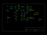
The snubber serves a different purpose. The model is intended to show the influence of caps that are immediately adjacent to the fet on the PCB. They play a significant role in reducing the peak voltage seen at the cap due to remaining inductance in the input filter caps themselves as well as trace inductance between the input filter caps and the FET. I've modeled a nominal 10nH here, and that may be optimistic, depending on the board layout.
I don't think it's realistic to expect anything smaller than several hundred nH of inductance on the battery wires, so the 200 nH of your sim is probably optimistic.
It was the smallest source inductance that I could bear to model without cringing. Here's another model run that raises the battery inductance to 1uH, and raises the input cap to 2 mF to represent a larger array of caps to spread out the input current. The effect is pretty dramatic. Effectively the cap current becomes a square wave, with the battery pack current being relatively constant. Therefore, putting a current clamp on your battery wire and measuring the ripple on a 'scope should give a good indication of how well the wiring has been routed.

Postby liveforphysics » Fri Apr 29, 2011 1:51 pm
When you change the value for L4 to be more representative, you will find the cap spikes decrease. ...
Try changing L4 to 450uH, and R5 to be 280mOhm. Those are fairly typical hubmotor values.
rhitee05 wrote: LFP, I don't like to be contrary, but I don't think the larger values of L4/R5 will make as large a difference as you expect to the currents in the decoupling cap. I'd be interested to see jdb try a different set of values, but I wouldn't expect to see a large difference.
There is almost no effect on the voltage spikes whatsoever. The principle effect of increasing the motor inductance is to reduce the ripple current in the motor windings themselves. It also reduces the ripple voltage seen at the filter caps to a point, but this isn't where the damage is being done. I did not increase the winding resistance, even though it would probably be appropriate, just to avoid rebalancing the BEMF.

Now on to the really interesting changes. I replaced the ideal freewheeling diode with a second identical FET, with the gate held to zero. My original intent was to check for dV/dt-induced turn-on of the low-side FET, but instead I discovered something else. The body diode takes a non-zero amount of time to switch off, which IR has been kind enough to provide in their SPICE model. The effect is that there are two voltage spikes to deal with: one when the high-side fet is turned off, and another when it is turned on. At the same time, I had also modeled the inductance of that film snubber cap. The result is... pretty dramatic. I started seeing these extra-large voltage spikes on the turn-on, and ran a short-run high-resolution test of one PWM cycle to take a closer look.

I guess that's how SPICE shows something blowing up

. The voltage is clipped on the high-side due to the reverse breakdown of the low-side FET. This is the voltage that would be measured on the fet's package pin, not the controller's input terminals.
So, what cap has the smallest ESL? An MLCC, of course, as fetcher pointed out above. A relatively standard 1210 2.2uF 100V MLCC cap from Kemit comes in at a 0.8 nH package inductance, and 1MHz ESR of only 6 mOhm. And it totally saves the day.


So, the lessons: Attention to detail on the board with the caps that sit immediately adjacent to the fets also has a strong influence on the fets' survivability. Higher-capacity low-ESR input filter caps do help to decouple the battery from the controller, but there is still some remaining inductance that must be addressed by low-ESL low-ESR smaller caps.
Second, the body diode of a power MOSFET may be a relatively low-performance P-N junction. There is a short-duration shoot-through current during high-side turn-on (and low-side reverse recovery) that makes the snubber's job much harder. In this particular sim, the peak current is 2x the winding current, for 4x the energy storage required to avoid a breakdown of the low-side diode. It might be interesting to take a 6*N-FET Infineon (or one of its clones) and populate it with 6*(N-1) FET's and 6 Schottky diodes, assuming you can find parts that are pinwise compatible with TO-220 (I haven't checked). Slowing down the switching speed does help a little bit, but at a much higher switching loss penalty.

")