Version 2 Crystalyte Controller information

Hi Guys,

I'm having a problem with my V2 controllers running 4110 FETs at around 72V and 50A.

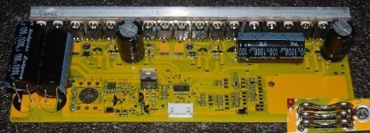
After taking one apart I noticed that the leg of the Cap in the photo had blown off and I'm assuming that one of the FETs is shorting due to the wheel being very hard to turn. Also, the rest of the board looks totally fine... no signs of overheating at all, so I'm assuming it's a shorted FET.

I had a similar problem with a controller a while back which blew the other 2 capacitors on the board but continued to run until what I would assume was a spike also blew or shorted the FETs......... See the first few pages of this thread..... Those 2 caps appear to be fine this time.

I'm assuming the capacitor went first just by flicking through this thread, but I can't exactly work out how to stop it from happening again.... I mean... put larger capacitors in it seems obvious, but what values? Run them in series or parallel? I'm assuming that a shorter battery lead also makes a difference.

One thing to note is that in my application the wheel might leave the ground for 2-3 seconds with the throttle held on full, and then hit the ground again while still at full throttle. I know this is most likely what is doing it, but rather than change the riding technique how can I make the controller resistant to this type of abuse?

If any response could be given in laymans terms it would be much appreciated.

 
The way that one broke looks like the result of vibration and fatigue in the wire. The capacitors need to be glued to the board so they can't wiggle.
 
So you think that's all it is?

It is a possibility because the bike was getting some serious air before it happened.....any tips on the quickest way to locate a blown fet?
 
Fechter's the expert but, on my board, all three leads of the blow FETs were shorted. Just ohm them out and you'll see zero resistance across any given pair of leads. Of course, that's not all that blew on my board. I'm waiting for my new controller to arrive from Knuckles.
 
getadirtbike said:
Ok, so Knuckles sounds like he's the man. What do his controllers have that all the others don't??
They are way cheaper than C'lyte and, hopefully, way more reliable than my C'lyte ver. 2 controller.

I think my Infineon will ship from China any day now.
http://endless-sphere.com/forums/viewtopic.php?f=2&t=5713
 
Right, blown FETs will have shorts between all the legs typically. The gate resistors blow on the V.1 controllers. You can also measure resistance between each phase wire and each power wire to locate which phase is shorted. When measuring, reverse the test probes. A shorted FET will be zero in both directions. A good one behaves like a diode and will have continuity in one direciton.

I've seen vibration cause many failures. Anything that can wiggle will, and copper doesn't like getting bent back and forth too many times. Once the cap lets go, then there's no protection for the FETs. The capacitors on the V.2 controllers have a very high failure rate even if the legs stay intact. I think they are just poor quality.

The Knuckles controllers aren't perfect either, but they have two important features:
1. a proven track record.
2. they are so cheap that if one (or two) blows up, it's still cheaper than a Crystalyte.

They also seem to have very effective self-protection features that tolerate nasty things like shorted motors.
 
Not without modification. If you replace the FETs with 4110s, it should be no problem.

You will need to ask Knuckles what the present models can handle.

They are working on a 24 FET monster version:
That should do it right out of the box :twisted:
24 FET infineon.jpg
 
fechter said:
Not without modification. If you replace the FETs with 4110s, it should be no problem.

You will need to ask Knuckles what the present models can handle.

They are working on a 24 FET monster version:
That should do it right out of the box :twisted:

Wow how sweet is that.
 
holy cow, i thought our 12 fets crystalyte was crazy, 24 fets. I hot glue those caps to my board to keep them from moving around. Since they failed so much i usually put caps with twice the rated voltage of what voltage i'm running.
 
ngocthach1130 said:
holy cow, i thought our 12 fets crystalyte was crazy, 24 fets. I hot glue those caps to my board to keep them from moving around. Since they failed so much i usually put caps with twice the rated voltage of what voltage i'm running.

My bad,

it's ONLY 18 FETs. Imagine what you could pump through 18 4110's :twisted:
 
Killed another 4110 controller yesterday.... had the caps glued down so that that they couldn't move and it ran fine under heavy load at around 60A.... there were no issues at all.... until we started with the wheelies..... always with the wheelies.

From memory I was having caps blow and then that was causing the fets to go.

Appears to be the transient loading that has been discussed here earlier.

Anyone know which of the caps I need to pimp up to try and stop this from happening? There are 2 together and then the one on its own like in the photo that I posted a few days ago...... or do they all need replacing?
 
I think 60amps way to much for that board unless some heavy duty soldering put on there, and a bridge for the high amp track across the board, its only designed for 50amp max and 35amp is safe level. I think would be hard to get working reliably on 60amps. anyone got an 18 fet controller infineon controller yet? any ideas of cost?
 
60A hasn't been a problem at all as far as heat etc are concerned... the last 3-4, 4110 controllers that i killed were doing wheelies... or just people flicking the throttle on and off from standstill..... doesn't appear to be related to high loading in any way....

Who exactly manufactures the Infineons anyway?
 
There has been a lot of talk in this thread about that subject IIRC
Search this thread for "low ESR" and you will find what you are looking for.
Values and voltages are not that critical.
This may be the odd case where bigger is actually better.
 
i had similar problems of 4110 FETs blowing out. my solution to this was to add 1/4W 22R resistors in series with the gate of each of the FETs. i did it the lazy way. i just unsoldered the gate leads from the board, lifted them out of the hole and added axial lead resistors in series.

I got this tip from some International Rectifier app-note that i can't find at the moment. they recommended that parallel FETs need the gates isolated from each other when using 10R to 50R resistors. i had some 22R handy so i used them.

rick
 
i finally got some time with a borrowed microscope and had a look at those SOT23 transistors used in the driver stages of the controller.

all of the ones designated Tx ("T" followed by a number) on the board are MBT8550. this is a PNP switch. i could not find them in stock anywhere. there is a replacemet from Fairchild KSA1298 that mouser stocks for about 7 cents each.

all of the ones designated Nx ("N" followed by a number) on the board are MBT8050. this is NPN compliment to the MBT8550 switch. i could not find them in stock anywhere either. there is a replacemet from Fairchild KSC3265 that mouser also stocks for about 7 cents each.

also all of the SMT capacitors designated Kx are marked as 103.

i discovered that it is much easier to read this crap when using a properly adjusted polarizing filter and about 20X magnification

rick

Fechter - maybe there should be a sub-topic that contains only the schematics and part values. it is getting tough to wade through almost 30 pages to find a little schematic segment buried somewhere in there.
 
rick i'm quite interested in that application note on the gate resistors, you are talking about the v2 board?
you added some resistors in series? each fet pair has only one gate resistor they share, can you elaborate a little on what you did?
 
I think that the issue is that they don't really have a "GATE RESISTOR" comon or otherwise.

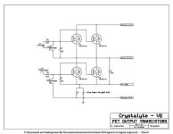
check out this fragment of the schematic:

original fet.jpg

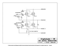
now for the changes to isolate the gates:

modified.jpg

I'm sorry that i cannot find the original IR app-note. i recently upgraded my laptop and when i was ttransfering files i did a major cleanup and re-organization. i think i re-organized that note out of existance.

the thought behind the separate gate resistors was that although they are very similar the fets are not identical matched sets. one in each pair will always turn on faster. if the gates are not isolated the one that turns on faster will hog all of the drive current prveventing the other one from turning on. so the one that turns on first will carry the entire load and can fail. once it fails the other one will then have its turn to carry the load by itself and it will also blow.

isolating the drive to the fets will slow down the turn on and prevent one fet from hogging all of the drive current.

at least i think that was the point of the app-note when using multiple parallel fets. my understanding of this is far from complete and maybe one of the engineers would be better qualified to explain this or posibly debunk this. in my limited experience my controller has not let out the magic smoke since i made this mod.

rick

or maybe i am taking it easier on my controller and not abusing it so much?
 
HI Rick
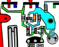
thanks for detailed answer, I did a schematic also!! I just took a pic of the board and then coloured in the bits, gate resistor seems to be in different position to your dia ( i.e. last component before the fets), if your board is same as this, not sure will make any difference to your mod. Seems there is a newer version of the board out also, will try get some and see if they have changed gate resistor section.
first fet pair v2.jpg
 
the point of the app-note was to get the resistance separating the gate of one fet from the other. putting some electrical distance between them so to say.

desoldering the gate lead and lifting it out and then soldering a 22R resistor from the hole in the board to the lifted gate lead would do that.

rick
 
Back
Top