Version 2 Crystalyte Controller information

Just wanted to add some further insights and explanations for the need of individual gate resistors for the power MOSFETs.
All the posts here are truly remarkable. So I took the opportunity to collate all the suggested changes into a single PDF along with some design reflections of my own. Please feel free to add or modify anything in the attached document.

Cheers,
Sol
 

Attachments

  • crystalyte_v2_changes_rev2.pdf
    899.5 KB · Views: 439
Nice job and welcome to the forum. I'd like to take a summary like that and post it in the Technical Reference section. I'll see if I can port the .pdf file.
 
Hello,

I've read nearly 7 hours about the Controller now. I must say it hides most of it's features if you do not ask or read about it :wink: .So i will aks about a nice feature.
On my papers (pin settings) it says that you can use a kind of tachometer. Can anybody tell me how to use it?

I must tell you that this forum is exceptionally great and that you really help me in developing the hardware for our "multi-powersource-vehicle", e.g. Fuel-Cell, LiIonMn and Solar.


Thanks a lot.

Elektrofreak
 
Sol said:
Just wanted to add some further insights...

Good job Sol.

When a forum gets as big as this one is starting to get we almost need someone to do a nice job like you did, then post the most current "summary" to the first post. You see this a lot on RC Groups or Reef Central where the threads regularly get to be hundreds of pages long.

I guess the counter argument would be that people should be forced to do the work to extract the information themselves thereby gaining an education in the process. You see this a lot in automotive forums where it is important for people to understand exactly *why* they are doing this or that to an engine.

In this case, the subject is already so "DIY" that if someone is looking for the information and prepared to use it then we can assume that they are the type that will educate themselves without being forced to do so.

Ok, now hurry up and get to work, you have about 50 other major threads that need servicing :mrgreen: :wink:

-methods
 
Welcome Sol,

That's verY generous from you to spend time like that and to share that at your first post!! Nice summary!

Maybe i should give that to John (Oyeah), he have direct contact with the crystalyte staff and he is now working on asking them to build a 18 mosfet version of the existing 12 mosfet controller :twisted: for a future mooded version of the 5305... the 5303/06 serie parallel motor!!.. just like tsome NEDRA EV race use for getting more troque and then speed!

Doc
 
markcycle said:
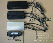
crystalyte has a 18 Fet controller see picture

A) 18 Fet

B) 12 Fet

Hey Mark, that's great!

Does the A) 18 mosfet is made of 4110??.. and why it is only rated 48A???

the one i'm talking about will have higher current capability using 18x 4110.

Where did you got it?

Doc
 
Hey doc, are you aware that electric rider has a new prototype X5 with disk brakes?
They said it will be available in a few months.
Custom designed through Crystalyte

I tried to talk to them about all the things we want . . . you know. . . rolled threads, better wire, built in torque arms, longer shafts, better heat management, etc.
As expected they have to cater to 90% of their customer base which are "normal people" who want to get into a powerful ebike for as cheap as possible
Cant knock that, business is business.

Ya know Doc, I know a lot of RC guys who re-wind motors. There is one fellow in particular who is "the man" not far from me. Perhaps I could convince him to rewind my X5. Do you have any sort of plans or calculations? He once rewound a 16 gram Hobby City motor for me and the difference was night and day. Only charged me $20 too! (for the motor, parts, and labor)

-methods
 
Doctorbass said:
markcycle said:
crystalyte has a 18 Fet controller see picture

A) 18 Fet

B) 12 Fet

Hey Mark, that's great!

Does the A) 18 mosfet is made of 4110??.. and why it is only rated 48A???

the one i'm talking about will have higher current capability using 18x 4110.

Where did you got it?

Doc


I got the picture from Crystalyte when I was considering there controller for my motorcycle hub motor but I decided to stay with a Kelly controller

I don't know the type of Fet in the controller. I also think they derate these units because they don't use large enough wire size for the phase wires and the PC board traces can't handle the current even with wire overlay.

Mark

I don't know the type of Fet
 
I wonder if they set it up as 2 fets on the high side and 3 on the low side?

i have seen some of those cheap scooter controllers set up as 9 fet units. ie. 1 high side fet and 2 low side fets on each phase. these ones had no labels or markings. but i was told they were supposed to be 48V 30A units. board layout and part numbers were similar to but not identical to the Crystalyte V2 controller.

rick
 
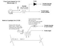
Ever wondered how to connect the Cycle Analyst CA-DC throttle over-ride to a Crystalyte Ver2 controller?
It's simple if you have some soldering skills and good eyesight. My circuit is a little different from the Cycle Analyst manual. I found that connecting to XS+ and a diode parallel to the on-board 20K resistor R39 (as shown in some photos in this thread) disabled the controller. After a bit of tweaking I got it going. Here's how:

Throttle Over-ride (reduced).jpg

I have found that a 5K6 resistor works best, the throttle has full linear control from off to full on.
Make sure that that the diode direction is correct and be very careful when removing the surface mount resistor R39. Heat both sides evenly and remove using fine tweezers.

Getting this going has now made it a no brainer for me to get home with a 10AH battery for 27 Km and 1200ft of total climb. Just set Speed Limit to 35 Kmh and Max Amps to 20. Prior to getting this going I had to be careful not to floor it from each stop and not cruise at 40 Kmh or I would run out of charge.
IMHO I reckon that the CA must be the best thing since sliced bread and Vegemite. Hats off to Justin. Justin, you are the ultimate Ebike hero. :D
 
back in August of 2007 Justin Lemire of e-bikes.ca and the designer of the CA posted this schematic of the mods to the V2 controller for the additional e-brake line.


the link for this post is:
http://www.endless-sphere.com/forums/viewtopic.php?f=2&t=2038&st=0&sk=t&sd=a&hilit=rfw4850&start=15

it shows that the R39 resistor is replaced by the diode. i did this on a couple of V2 controllers and it worked fine as the e-brake signal. until yesterday i did not have a CA to play with. i have a couple of the good old reliable (read "antique") drain-brains that do not have the built in limiting functions.

so i am wondering why is the 5.6K resistor necessary? is the limiting action too harsh without it? does it work without the 5.6k resistor in series with the CA?

rick
 
Hi Rick,
You are suggesting that it is to be used as the ebrake signal with R39 replaced by a diode. If you are using the brake lever switches on this line, you are grounding the throttle line which is the same as turning the throttle off. The correct ebrake inputs on the Crystalyte Ver2 controller are HH (switched to +5V to brake) or HL (switched to ground to brake). If the ABS line is grounded, either HH or HL when activated will also activate regen.
It may be that using the term "ebrake" here is a misnomer created by the manufacturer's "Chinglish", with Justin using it initially, but now using the correct term "throttle over-ride."

I initially used the schematic supplied in the CA manual Ver 2, but found it put the controller into an error mode and wouldn't start again without a power down reset. (On seeing your circuit, it was probably just the CA killing the SP line, if I had disconnected it, the controller would have started again). I then tried the version shown in the picture of lazarus2405's article in this thread where the R39 resistor is replaced by a diode between XS+ and the R39's inner pad.
http://www.endless-sphere.com/forums/viewtopic.php?f=2&t=3896#p58220

That gave the same result of stopping the controller. I then set up a small break-out cable to fit between the CA's connector and the controller. A 10K trimpot set up as a reostat was placed in the CA throttle over-ride line. At zero ohms the fault remained. I increased the resistance and found that a measurement where it worked properly without killing the controller was measured at 5416 ohms. I then installed the 5K6 resistor into the throttle over-ride line, removed the break out cable and the problem was gone, the controller worked and the Cycle Analyst did everything as promised. It maybe that the CA settings for ITermMax and ITermMin are wrong for my throttle. It was a generic brand supplied by solarbbq, I don't even know if it's a Hall-effect or potentiometer type. All I know is that it works. Depending on the throttle type, the 5K6 may or not be required. I'll have to investigate this aspect futher.
 
The v2 is New and improved.

1. The big cap is tied down with a zip tie. It may seem like no big deal but I fried two controllers because this thing broke loose.
2. Gaskets on the ends of the case.
3. Case has changed slightly (not necessarily an improvement, just a change).
4. Switch leads are dressed better.
 
Thanks Doctorbass, I have searched to no end for the info here using the search and keyword. I'm trying to find out what the stock fets are and who's been sucessful running 84v through a V2 controller. I read through 16 pages of results to find some info but still not sure about the fets. I went ahead and ran the bike at 84v with good results, will keep you posted on the long term durability.

Doctorbass, thankyou for your help and you have been a inspiration to me and my ebike. I enjoyed the drag race video and looking forward to the next drag race you are doing on june 23rd! :D
 
on the older Crystalyte digital controllers the stock FETs for 72V were the IRFB4710 on the oldest ones and the IRFB4310 on the later ones. but the last ones i saw were purchased almost a year ago.

both of these are rated for 100V so 84V would be fine.

rick
 
Thanks Rick, I appreciate that.

Any chance that 8 x SLA is safe? (100v)

My unmodified shunt is pulling around 48A max. I don't plan on changing it.

Regards,
Justin
 
not really. 8 SLA's hot off the charger will be over 14V and will settle at 13.5V each. that exceeds the 100V maximum rating of the FET.

may work for a while but will not work for long.

rick
 
Hello,

few days ago I received crystalyte 4850 controller. Today I opened controller box and found that it has PCB marked: RFW4850-V08 050809 REFLY. I haven't seen this version in this forum. I have the following problem: this controller don't start immediate my crystalyte 408 motor, motor starts only when i manualy turn it. What to look for to solve this problem?
 
dexterlt said:
Hello,

few days ago I received crystalyte 4850 controller. Today I opened controller box and found that it has PCB marked: RFW4850-V08 050809 REFLY. I haven't seen this version in this forum. I have the following problem: this controller don't start immediate my crystalyte 408 motor, motor starts only when i manualy turn it. What to look for to solve this problem?

you look in the motor. i had this same proble with a couple of motors when first using one of the digital controllers last year. at first i also suspected the controller. worse yet the controller would work with some motors but not with others. exactly as you describe, the motors would run if i gave them a flick but would not start by themselves. once running they would run perfectly until the motor stopped.

by accident i damaged the wiring and one of the hall sensors in one of the motors. i was checking the wiring to see if it was the problem. i figured - in for a penny, in for a pound - and i replaced all of the hall sensors. surprise, surprise the motor now ran perfectly. i replaced the sensors in another misbehaving motor, no surprise, it also started to work.

not all hall sensors are created equal. have seen many on crystalyte motors that do not work as spec'd. i tested the sensors i removed from the motor and i found that they would change state randomly when they should be locked on or off.

the problem was made worse at lower voltages. the older Analog Crystalyte controller powers the halls with 12V and the newer digital uses 5V. the offending sensors were worse at 5V.

so at least in my case the issue was not a bad controller but marginal hall sensors in the motor.

rick
 
Could you help me to set the LVC control of my NINE?

The picture of 48v Nine Controller:

www.3darea.it/ftp/MASSI/IMG_1920.JPG
www.3darea.it/ftp/MASSI/IMG_1919.JPG
http://www.3darea.it/ftp/MASSI/IMG_1925.JPG
http://www.3darea.it/ftp/MASSI/IMG_1926.JPG
http://www.3darea.it/ftp/MASSI/IMG_1927.JPG
http://www.3darea.it/ftp/MASSI/IMG_1928.JPG
http://www.3darea.it/ftp/MASSI/IMG_1929.JPG
http://www.3darea.it/ftp/MASSI/IMG_1930.JPG
http://www.3darea.it/ftp/MASSI/IMG_1931.JPG
http://www.3darea.it/ftp/MASSI/IMG_1932.JPG

Thank you
 
psicoticos said:
Could you help me to set the LVC control of my NINE?

The picture of 48v Nine Controller:

http://www.3darea.it/ftp/MASSI/IMG_1920.JPG
http://www.3darea.it/ftp/MASSI/IMG_1919.JPG
http://www.3darea.it/ftp/MASSI/IMG_1925.JPG
http://www.3darea.it/ftp/MASSI/IMG_1926.JPG
http://www.3darea.it/ftp/MASSI/IMG_1927.JPG
http://www.3darea.it/ftp/MASSI/IMG_1928.JPG
http://www.3darea.it/ftp/MASSI/IMG_1929.JPG
http://www.3darea.it/ftp/MASSI/IMG_1930.JPG
http://www.3darea.it/ftp/MASSI/IMG_1931.JPG
http://www.3darea.it/ftp/MASSI/IMG_1932.JPG

Thank you

okay you are new. but there is a proper etiquette and protocol. in order to keep information organised and easier to follow it is important to stay on topic. in this case your motor controller is not and has absolutetly nothing to do with The Crystalyte Version 2 Brushless controller. this thread is specifically for questions about one specific model of controller - The Crystalyte Version 2 Brushless controller

I think that you should start a new thread asking about your controller and delete this post from this thread.

a little more information may also help. such as why you want to lower the LVC. are you trying to use thw 48V controller with a lower voltage pack? how low do you want to go? 24V? 36V? what was the source of the controller?

nice pictures, though. but please do not HIJACK an established thread.

rick
 
Back
Top