Version 2 Crystalyte Controller information

kbarrett said:
The only weak point I see in mine for water is the red on-off rocker switch. Everywhere else was easy ... I just used a bead of silicone sealer before re-assembling.

For the red button, I have not yet done this, but am looking for a soft round rubber cover that i can glue to the controller box to cover the button.. will let you know when i find the right size shape ! hehe..
 
Ypedal said:
For the red button, I have not yet done this, but am looking for a soft round rubber cover that i can glue to the controller box to cover the button.. will let you know when i find the right size shape ! hehe..

i just ditch the switch. plug the hole with a big blob of silicone. for the on/off switch i just extend the 2 wires outside of the box to a frame mounted key switch.

rick
 
you could buy those reed switch. Then mount it at the whole where the old switch used to be. Reed switch is activated by a magnet. A unique activation system. Don't think thieves walk around with magnet in there pocket.
 
Hi, I'm new to E-bikes, and new to the forum. I have been overwhelmed with info and great links since finding this forum.
You guys also rock when it comes to technical expertise and schematics, and this is why I am posting.....
I have a V2 controller that worked fine when I first hooked it up, but I was unsatisfied with the physical layout of where I would mount it. When I hooked it up again, I got nothing.... not even lights.
I am frustrated with tech support from the guys I bought it from (who shall remain nameless for now) and have carefully open the case. I have traced the input of 52V past the switch, but don't know where to keep chasing the voltage from here. Are there any protection diodes for the input? What is the most likely component to fail and cause zero life on the controller?
When you guys talk about the error codes on the LED's- is that for the main (outside visible) LED, or the one to the upper left of the Cypress chip?
Any ideas would be great.
If anyone wants to walk me through this unit, They can call me collect! I'll send beer!
Thanks,
Tim
 
If you look back on page 2, theres a schematic of the voltage regulator. The switched power goes to the voltage regulator. It sounds like the regulator has no output. Yes, the LED is the one on the outside (I think).
 
I think its the one on the inside, but must confess i've never watched the outside one when errors were reported..
 
Thanks, trying to work through this as I write. Is is mandatory that the throttle, motor, or hall effect sensors be attached for the controller to operate? or can just the battery connection alone be used? Thanks
DSCF0158.jpg
 
aw crap, you have the 6 version fet set up. so far i have two of those that are junk one a 6 and one a 12 fet. Im on my third and right out of the box i have problems , its with pluging in the cables, loose conections inside the controller. I dont think i like this new model controller. I was thinking that i was bringing on the problems myself but i wonder now...My wifes bike has the old anolog and it works super all the time.. for the money these cost you would think there would be better QC. I just cant get into my mind why a 50 amp controller comes with such crappy output wires
 
Thanks for all the input.... It looks like the LV regulators have blown, Damn near right out of the box.
I'm not at all impressed either. If I fix this one, can I populate the other 6 FET's without doing any other mods?

Different topic, but If I don't fix this one, Before I blow $$ on another version and find out it is crap, what do you recommend?
I've seen that lots of people are running some serious mods, but what is a great step up from this P.O.S.?
I'm running a Crystalyte 5303 front hub, with 48V 12A SLA's (soon to be upgraded to nimhi or LiPO4) open to suggestions!
If you were in the market for another controller, would you consider the Golden motor controllers, or this one
http://endless-sphere.com/forums/viewtopic.php?f=2&t=4109
It would be great to see a "best of ranking" so we newbies can compare before we get buyers remorse like I do now....
Thanks for the help!
 
That's really the problem with ebikes in general. All the hardware is poorly designed.
A ranking system to determine which one sucks the least would be good.

You could get a really really expensive Sevcon PMAC controller and only the price would suck.

The Shenzhen controllers you mention don't have much track record yet.

Hmmm... I think we need a guinea pig here.
 
fechter said:
That's really the problem with ebikes in general. All the hardware is poorly designed.
A ranking system to determine which one sucks the least would be good.

You could get a really really expensive Sevcon PMAC controller and only the price would suck.

The Shenzhen controllers you mention don't have much track record yet.

Hmmm... I think we need a guinea pig here.

Heck will that controller work with out motors, ive spent well over 7oo so far on controllers.
 
I was also wondering about this with the new controller. Is it possible that with the 14 or 12 gage wire feeding the motor that when under a load and when they heat up its like a resistor to the controller and when you upgrade to # 10 wire the resistance is now gone and the controller now takes the death hit. Both my controllers meant there maker after i upgraded to # 10 wire. one worked about 2 weeks and the other for about three days. there was no solder spits any where but the fets died. replaced the fets and burnt out two hall sensors. when i applied power to wheel. I know i suck at this electrical stuff but i can solder decent. lol

Heck this new 48 amp controller has the same crap ass wire feeds and they get warm as hell but there is no way Im going to upgrade the wires on this one. At least not until i find out whats going on.lol
 
diver said:
I was also wondering about this with the new controller. Is it possible that with the 14 or 12 gage wire feeding the motor that when under a load and when they heat up its like a resistor to the controller and when you upgrade to # 10 wire the resistance is now gone and the controller now takes the death hit. Both my controllers meant there maker after i upgraded to # 10 wire.

If that holds weight, then it sounds like filter caps aren't doing their job. That is, if there's a causative link between the wire upgrade and blowing your controllers.

It looks like the LV regulators have blown,

Make sure you have battery voltage at the controller. From the sound of it you have a bad connection or blown fuse. Unless you meant you were 'chasing' the voltage with a multimeter and not just your eye.

If you have battery voltage across the bus but no voltage across anu +5v and any GND, you've got problems.

The error codes are displayed from the LED by the Cypress chip. I've had enough of 'em... :evil:

The guys you bought it from should not remain nameless. There's a lot of awful support oit there that needs to be exposed.

As far as rankings, this unit is actually one of the pretty good ones. Though, you might want to look at Kelly ebike controller, though they're pretty expensive.

You can populate those other 6 FETs with no problems. Just make sure the solder at the source and drain legs is as thick as you can get it without shorting.
 
I think if anyone is still getting 6 fet v2 controllers from anywhere thats just plain wrong!!
I would send back and get 12 fet version asap
anyone try the abs pin as yet? I dont have any v2 controllers to try it, should have some soon I'll give it a go
what would be the ideal caps to put in these? I've looked up about low esr caps but which ones would be suitable,
the small red caps, would leave them in place and add additional ones parallel or completely replace,? I think this controller might be pretty good for lower amp use with good caps? needs beefing up solder on fets for higher amps.
do low esr caps have special markings on them or just look like normal caps?
 
That varies quite a bit. Some of them say "low ESR" right on them. Other similar types might be called "low impedance", "switching grade" or "computer grade"

I'm not sure where you order stuff down under, but from Mouser, here's a few likely candidates:
http://www.mouser.com/search/Default.aspx
647-UPW2C331MRD
647-UPJ2A471MHD
647-UVY2C331MHD

The little red ones are good. More would be better. Multilayer ceramics should be good.
 
This is an excellent thread that is contributed by all you guys.
So far I have spend many hours to study it and have gained a lot of insight about this V2 controller.

1) There are two versions- 12 FETs and 6 FETs. 6FETs version has their FETs mounted on the odd number position. Solarbbq2003 prefers 12 FETs version.

2)Rkosiorek gave a lot of technical information about the board. It has an 8bit RISC based core CPU running at 12Mhz . It also uses a hardware based PWM.

3) It has a 4 layer board. The S (source) legs of the low-side FETs (No 3 and No 7) are connected to the -ve bus via the inner copper layer. High current did blow the solder off at these S legs in several cases as reported by rsisson, brucey, solarbbq2003 etc.

4) At the instant of blowing off, the S leg of the FET is "disconnected" from the -ve bus. The inherit free-wheeling diode inside the FET is also disconnected and a very high voltage spike will be produced at the switching of the FETs. The high voltage spike may damage other good FET as reported by solarbbq2003 [Found a very small break in solder on bottom of board from middle leg of a fet from excess current, interestingly the fet where solder blew was ok, it was the other one that had blown in that pair.]

5) Lazarus2405 and others suggest that it is preferable to beef-up the high current tracks. The current tracks on the surfaces could be beef-uped with no problem. But it is not able to beef-up the current track in the inner layer. Solarbbq2003 soldered external wires between the S(source) legs of No 3 and No 7 FETs to the -ve bus using copper wires which I think it is a MUST for this version of controller. It should be done for 12 FET as well as for the 6 FET version.


6)Rkosiorek- [there is a 2.2K pull up at each of the hall sensors. there is also a 3.3k resistor in series from the hall sensor input to the Cypress chip and a 103 cap from the cypress input pin to ground.]
a) At the falling edge of the Hall signal, the 3.3k res and the 0.01uF cap will form a low pass filter with a 4.8kHz cut-off.
b) At the rising edge, the (2.2k + 3.3k) ohm and the 0.01 uF will a low pass-filter with a lower cut-off at 2.9kHz.

7) Fechter- [The Puma motor I have runs a ~5:1 gear reduction. Nominal rated hub rpm= 320.
There are 16 magnet poles (32 magnet segments) on the rotor, so that works out to ~427hz at 320 rpm. If you were running seriously overvolted, you might get up to ~800hz.]
The 4.8kHz LP filter may not cause too much delay for output frequency lower than 480Hz (using the rule of thumb of 10 times).
The 2.9kHz LP filter may not cause too much delay for output frequency lower than 290Hz. Definitely it will cause excess delay at 800Hz output.
Perhaps one may double the LP filter frequency by using 0,005uF instead of 0.01uF cap.
 

Attachments

  • PA270018 copy.jpg
    PA270018 copy.jpg
    83.3 KB · Views: 2,784
  • fet3 and 7 add shuntsmall copy.jpg
    fet3 and 7 add shuntsmall copy.jpg
    77.5 KB · Views: 2,827
I'm not so sure about the source connections. I think the board is two sided with no inner layers. The bus connecting the source leads is hidden under the solder mask and is hard to see. I will scrape one off to verify.
 
Rkosiorek said -[Unlike the old analog controller where the copper traces exist only on the top and bottom of the board (so we can actually see all of the traces), the V2 board is a 4 layer board.] -
 
The7 said:
Rkosiorek said -[Unlike the old analog controller where the copper traces exist only on the top and bottom of the board (so we can actually see all of the traces), the V2 board is a 4 layer board.] -

I dunno... I have a board here, and I can hold it up to a bright light and look through it.
I don't see anything that is not connected by one side or the other. I don't see any inner layers on the edge of the board either. Certainly all the FET connections are visible, but covered with the thick white solder mask.
 
Fechter,
I would concur with you that it is only 2-sided since you have examined the board carefully .

From the photos of the board, It seems that the S-legs of No 3 and No 7 are connected to the -ve bus on the component side via through-holes and tracks which are not beef-uped by "solder and wires".

All the other S-legs and D-legs are visibly connected via "beef-uped solder and/or wires" for high current purpose on the non-component side.

I think that the way of beef-up using external wires for S-legs of No 3 and No 7 as done by solarbbq2003 is still a MUST.
 

Attachments

  • PA270019 copy.jpg
    PA270019 copy.jpg
    45 KB · Views: 2,699
My two cents.....
I also have one of these V2 units (my LV reg blew on first time I hooked it up, see earlier posts) and 20 yrs ago I got my BSEE. (I have long since been neutered by project management) From my semi professional viewpoint, I seriously doubt it is a 4 layer board, both from personal observation(not thick enough) and the cost/benefit analysis. 4 layer boards are much more expensive to produce than a board that is twice as large. It would make more $$ and sense to put two- 2 layer boards in one case, a fine one for digital logic and a beefy one for power xfer.
4 layer boards create much higher QC rejection and manufacturing costs, and are only used when absolutely necessary. QC is obviously already an afterthought, as they are shipping marginal units with 6 FETS in a design for 12, and with a 4 layer board, I doubt 1 out of every 4 they produce would work out of the box. (wait-perhaps that is about what we are experiencing?)
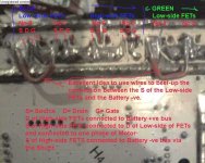
I believe Fechter is correct that the solder mask is covering the vias and many other traces that account for the missing connections.
Update: my v2 unit is out for warranty repair, and WILL be replaced with a 12 FET version, or I will reject it again!
Thanks for the help and support for someone who hasn't enjoyed their first mile of E-bike commuting. I am already planning a V2 build, even though I haven't finished V1.
I admire the engineering talent and user insight that shows up in this forum!
 
I have two of those V2 boards that i robed some of the parts off that i will give to anyone who wants them for cutting up or what ever.
 
diver said:
I have two of those V2 boards that i robed some of the parts off that i will give to anyone who wants them for cutting up or what ever.

I would like to have one of the board to investigate how the S-legs of No 3 and 7 are connected to the -ve bus.
I am in Vancouver BC.

Could you PM me?
 
Back
Top