bikerestorers said:Sorry one last thing. Why would you set the decline to 255 instead of 0? Do we know what the decline setting does?
I just like it this [snappy] way. You need to experiment. Does the same as the prev val, but on decel.
bikerestorers said:Sorry one last thing. Why would you set the decline to 255 instead of 0? Do we know what the decline setting does?
what exactly do you mean by "didn't helped" ? do you mean the wire had no continuity from connector to controller pcb? or that it did, but has no voltage on it from the controller? or what?SilentEnduro said:Thanks, checked, didn't helped.
the thing is that there is strange voltage on hall connector, between black-yellow - 0.7v, black-green - 4v, black-blur - 4.6v
Bartosh said:bikerestorers said:Sorry one last thing. Why would you set the decline to 255 instead of 0? Do we know what the decline setting does?
I just like it this [snappy] way. You need to experiment. Does the same as the prev val, but on decel.
bikerestorers said:Bartosh said:bikerestorers said:Sorry one last thing. Why would you set the decline to 255 instead of 0? Do we know what the decline setting does?
I just like it this [snappy] way. You need to experiment. Does the same as the prev val, but on decel.
Definitely best that way. I set the decline to 0 and probably as expected it did not decelerate!
larsb said:I guess that’s with no load ( not so important then)?
I’ve had my controller lose it at 6500 rpm at no load
amberwolf said:what exactly do you mean by "didn't helped" ? do you mean the wire had no continuity from connector to controller pcb? or that it did, but has no voltage on it from the controller? or what?SilentEnduro said:Thanks, checked, didn't helped.
if you don't tell us the complete exact results of your tests, or you don't do the tests, we can't know what's wrong to help you fix it.
the thing is that there is strange voltage on hall connector, between black-yellow - 0.7v, black-green - 4v, black-blur - 4.6v
taht's because there are pullups inside the controller for the signals, as motor halls do not output any voltage. they only ground the controller's built-in signal voltage when magnets pass them.
what the voltages you see probably indicate is the black yellow at the moment you checked it was near a magnet, so it was turned on, and grounding that signal. the green wasn't. the black-blur sounds like it's actually the hall power wire and not a signal. (colors of wires dont' necessarily represent the same thing on different controllers and motors; there are no official standards, and even if there were, no guarantee they get followed).
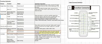
if you haven't already, i'd recommend checking the wiring diagram for the colors of the wires for each signal of that controller. if it doesn't have one you must open up the controller and trace the wires to make your own diagram. otherwise you can't know which wire is for which signal, and can't make the controller work as expected.

Bartosh said:bikerestorers said:Bartosh said:bikerestorers said:Sorry one last thing. Why would you set the decline to 255 instead of 0? Do we know what the decline setting does?
I just like it this [snappy] way. You need to experiment. Does the same as the prev val, but on decel.
Definitely best that way. I set the decline to 0 and probably as expected it did not decelerate!
yeah I was hoping you'd say that [; sorry :wink: been there
btw, to whom it may concern, 84V/300bA/500pA [9999], 5000 fw, loaded(!), couldn't stop my ride above 7000-7200 rpm. the controller gets confused, needs to be restarted, so be aware
yingyong said:Hello,from Thailand.
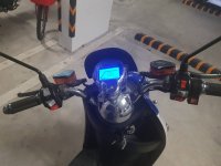
Need help for my China E-scooter with EM-50 controller. For what reason my Scooter now running with limit speed < 15km/h.
I read on "dineshmdes" table in page#2, right now controller faucet lock limit speed due to got some fault notification.
How to unlock speed limit? please advise. Thank you.
SilverLine said:yingyong said:Hello,from Thailand.
Need help for my China E-scooter with EM-50 controller. For what reason my Scooter now running with limit speed < 15km/h.
I read on "dineshmdes" table in page#2, right now controller faucet lock limit speed due to got some fault notification.
How to unlock speed limit? please advise. Thank you.
You need to post pictures of the pages, and the display Window.
SilverLine said::lol: :lol:
Come on man. How can we help you by looking at a picture of your scooter and keys.
Pictures of your settings on the controller
It may be. I measured both separately. Ramping could've been affected but I'm not sure... might have been the result of lowering the pA alone.larsb said:When i set tro to set mor than 9960 the value is not stored. I don’t think you can get higher.
Question is if it’s also relative to max battery current?
Amp meter with max val option, WOT and rolling. 300 bA is about 300 A measured. 9999 pA is about 360 A RMS measured so close enough for me.How do you measure? Seems difficult to get a stable value.
We need the peak value so rms times sqrt 2.larsb said:I think rms value is not correct since it’s three phase.