999zip999
100 TW
Alan B I do enjoy your input and your wisdom. I do enjoy the enlightenment your brain brings here 2 endless sphere. Thank you.
999zip999 said:Alan B I do enjoy your input and your wisdom. I do it enjoy the enlightenment your brain brings here 2 endless sphere. Thank you.
")
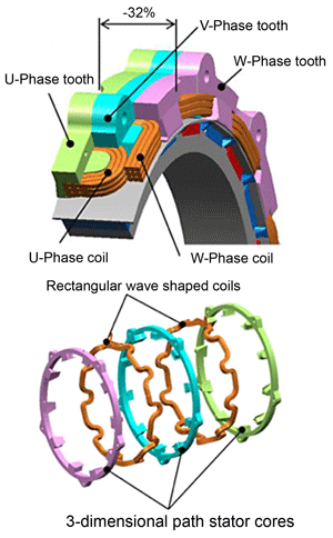
liveforphysics said:The performance dropping with SOC% is most efficiently solved by running a motor with 1 less turn, and having a bit more phase current.
It would be equally easy to make a 6s bike have identical performance from 100% to 1% SOC as any higher voltage vehicle system. Either way it's a ratio of pack voltage to motor BEMF.
The sort of components that would be required to pass this extra current and how it might the size/cost of the conplete system.cell_man said:Would love to hear some specifics, of how the controller would be approached

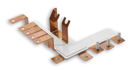
999zip999 said:Well who has a 1turn motor ? Sounds like a diy home brew.


999zip999 said:I want the honda one.