Why are my phase wires melting??

Comrade said:
Punx0r said:
Remember that phase current can be 2-3 times battery current...

How does current get doubled-tripled?

Probably several ways to explain it, and other members could likely provide more technical explanations, but I'll attempt to explain from a high school physics standpoint; conservation of energy.

  • If a bike has a 50V battery that is putting out 20A, that's 1000W going in to the controller.
  • A motor's speed is the result of the voltage provided by the (PWM) controller, which is lower than 50V at anything less than full throttle.
  • Energy required by the motor is based on load. 1000W in this case (conservation of energy, 1000W in, 1000W consumed)
  • If the controller is providing the motor less than 50V, say 20V for example, but the motor is consuming 1000W, then the current being provided to the motor would be 1000W/20V or 50A.
  • So, 20 battery amps, 50 motor amps.
 
E-HP said:
  • A motor's speed is the result of the voltage provided by the (PWM) controller, which is lower than 50V at anything less than full throttle.
  • If the controller is providing the motor less than 50V, say 20V for example, but the motor is consuming 1000W, then the current being provided to the motor would be 1000W/20V or 50A.

Are you sure the controller has the ability to control voltage? I thought it's just a bunch of MOSFETs that PWM the output of the battery, nothing more, nothing less.

So if the battery is able to deliver 20A, the phase wires will never see more than 20A. There is no any kind of step down or step up circuitry in the controller. Arguably the phase wires can even be thinner than battery wires, in the context of heating up, since any one of the 3 phase wires is only at 66% duty cycle.
 
Comrade said:
Are you sure the controller has the ability to control voltage? I thought it's just a bunch of MOSFETs that PWM the output of the battery, nothing more, nothing less.

So if the battery is able to deliver 20A, the phase wires will never see more than 20A. There is no any kind of step down or step up circuitry in the controller. Arguably the phase wires can even be thinner than battery wires, in the context of heating up, since any one of the 3 phase wires is only at 66% duty cycle.

Whatever makes sense to you :thumb:
 
Years ago, I took a proven formula of mid-speed Q100 geared mini-motor in a 26" whl. run on 52 Volts and a 17 Amp controller and swapped out the "260" motor for a high-speed "328" unit and the first moderate hill, the phase wires melted.
So what happened?
Graphing it out the Ebike CA sim, it was clear. The diminutive Q100 couldn't pull enough RPM's to get up into the "meat" of the powerband and the system, instead of being RPM limited, became Current limited. The controller, "seeing" the demand, was trying to supply max Amps on any kind of load. One thing about small motors, this kind of thing shows up real fast.
Not saying this is the case, or even much of a factor here, just something to think about.
 
When the controller is running at less than 100% duty cycle, it acts like a dc-dc buck converter. Energy is stored in the magnetic field of the motor windings and released during the off part of the cycle. At low motor RPMs, the phase current can be several times the battery current but at a lower voltage.
 
Comrade said:
Are you sure the controller has the ability to control voltage? I thought it's just a bunch of MOSFETs that PWM the output of the battery, nothing more, nothing less.

Exactly. That is how it is controlling the voltage. It increases the duty cycle of the battery-level voltage pulses, and the inductance of the motor smooths this PWM "squarewave" into a lower-voltage smoother waveform (not a steady DC because of how all of the involved components work).


So if the battery is able to deliver 20A, the phase wires will never see more than 20A.
No, because the changing voltage on the motor's inductance creates a changing current which can be much higher than the current out of the battery (becuase the voltage is less, and the power is "the same" (not counting losses), the current is more).

Additionally, the battery supply is on two wires, while the motor is supplied by switching between pairs out of three wires.

There is no any kind of step down or step up circuitry in the controller.
The controller and motor together *are* a conversion (step-up/down) circuit. That is specifically how PWM motor controllers work (for both brushless and brushed motors).


These are all things that people new to this stuff find hard to accept, but are true. THere are numerous threads about these types of things if you wish to poke around the forum.
 
amberwolf said:
These are all things that people new to this stuff find hard to accept, but are true. THere are numerous threads about these types of things if you wish to poke around the forum.

Thanks. I'm an engineer but not an electrical engineer, so the more complex concepts like electromagnetism are not easily deduced with just common sense. :lol:

I'll have to read up and maybe even test this on a bench, as I'm confused how low voltage and high current comes out of the motor back to the controller.
 
Comrade said:
amberwolf said:
These are all things that people new to this stuff find hard to accept, but are true. THere are numerous threads about these types of things if you wish to poke around the forum.

Thanks. I'm an engineer but not an electrical engineer, so the more complex concepts like electromagnetism are not easily deduced with just common sense. :lol:

I'll have to read up and maybe even test this on a bench, as I'm confused how low voltage and high current comes out of the motor back to the controller.

These concepts are taught in general engineering and science classes. I'd be surprised if any engineering school hasn't covered them. The physics explanation is something that falls under high school physics, which is why I chose to explain it that way.
 
E-HP said:
The physics explanation is something that falls under high school physics, which is why I chose to explain it that way.

Electromagnetism in high school? :shock:

Anyway, so if this 2-3 multiplier holds true, why are there plenty of pretty powerful controllers using Z9 connectors for the phases? I'm assuming ratings like 30-40A are for the battery side. If this gets multiplied on the phase wiring side, how does the Z9 hold up, since as Grin put it about the Z9 plug, "good for about 30-40 amps of max current".
 
Comrade said:
E-HP said:
The physics explanation is something that falls under high school physics, which is why I chose to explain it that way.

Electromagnetism in high school? :shock:

Perhaps the quality of a high school education has deteriorated over the last 45 years. Maybe the same holds true for engineering classes.
 
spinningmagnets said:
The names "phase current" and "battery current" don't make sense to me

battery current = current on the battery 2 wires, positive and negative

phase current = current on the 3 phase wires going to the motor
 
E-HP said:
Perhaps the quality of a high school education has deteriorated over the last 45 years. Maybe the same holds true for engineering classes.

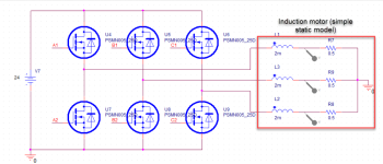
Perhaps. Do you mind pointing out on his diagram which wires will experience 2-3 times the amps when the motor is under heavy load?

1.png

Say the DC battery is able to provide 20A max. I'd like to understand where there will be 40-60A on any of the external wires.
 
Comrade said:
E-HP said:
Perhaps the quality of a high school education has deteriorated over the last 45 years. Maybe the same holds true for engineering classes.

Perhaps. Do you mind pointing out on his diagram which wires will experience 2-3 times the amps when the motor is under heavy load?

1.png

Say the DC battery is able to provide 20A max. I'd like to understand where there will be 40-60A on any of the external wires.

The three phase wires going into the motor/inductor. It's an inductive load, so even when the mosfet switches off, the current still flows, so there's more current on the phase wire, since it's still flowing when the battery wire is switched off.
This is a pretty good article, mainly because of the diagrams of the current flowing when the mosfet is switched on vs off:
https://www.celeramotion.com/ingenia/support/technical-papers/understanding-why-motor-phase-current-is-different-than-power-supply-current/

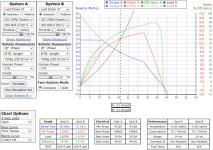
EDIT: I know with the controller I use now, vs the KT controller I was using before, I can set the max battery current to 30A to match the KT, but if I set the phase amps to 90A, the bike accelerates way faster than the KT. So, even when limiting the battery current, when you have a high load (hill, accelerating, etc.), the controller with higher phase amps has an advantage. I pay more attention to that now when looking at controllers. Without limiting the currents, my controller is rated at 70A continuous battery, with a 200A phase amp limit.

You can see how much more torque there is up to about 12 mph, when accelerating up a hill (high load):
Phase Amps.jpg
 
So we are talking about back EMF that is being snubbed by the body diode in the MOSFETs. Sure, that can peak pretty high, but what is the RMS in a typical hub motor set up since we are discussing melting wires?
 
The RMS phase current can be several times the battery current at low speeds. If you look at a scope trace, the PWM is just ripple on the phase current. At high PWM frequencies, it can be nearly smooth. So the phase wires can really get hot if you keep it at full current and low speed for any length of time. The motor windings will also be getting very hot. Once you get up to speed, the phase current gets closer to the battery current and will be equal when PWM reaches 100%.

When climbing very steep hills with my direct drive hub motor bike, I was limited by heat buildup. If I could maintain over 10mph, it could go for a long time without overheating.
 
I do have a scope so we'll get some real numbers once China Post delivers my motor. :mrgreen:
 
If you do your testing using a brushed motor and controller, it will be much simpler to see.

The same principles apply to the brushless multiphase motors, just for two phases at a time.

As a simplified analogy, you can think of a 3phase bldc controller as three brushed motor controllers operated by a master controller that detects motor rotation position and timing and directs the bridges of the three brushed controllers to commutate the 3phase motor correctly.

If he still has it available, Richard at 4qd.co.uk has had some very detailed information about brushed motor control, including detailed operational info and failure modes of older versions of the 2qd controllers. There also used to be a paid access Members portion of the site that even had older version schematics for those, along with even more info amounting to a motor control learning course.

I took a peek and the site has changed, but you could start here
https://www.4qd.co.uk/docs/what-is-pwm/
and here
https://www.4qd.co.uk/docs/battery-current-and-motor-current-tour-4/
and see if there is more detailed info if what is there is not sufficient. (I haven't read anythign on the new site).
 
Sounds of weird but I use the xt60 for connector for connectors. Thermally resistant plastic double surface area on contacts if you have a couple old controllers sitting around pulling from there
 
Last edited by a moderator:
Back
Top