Xlyte EB312 5v regulator problems

Lussy

100 mW
Joined
Oct 20, 2012
Messages
38
Location
New Zealand
Hi,
I have built a new bike (HS3540) with xlyte 48v,45amp controller.The bike was working great but wouldn't start after charging. I am trialing the xlyte APM dispaly, and it is not showing either "pass" or "Detection" when on. This fault check has worked well to show equipment faiures/shorts and connection problems in the past The battery is a headway 16s lifepo4 charged to a maximum of 60v during balancing (is this too high for a 48v controller, caps stamped 63v?). I recently increased the charge voltage to 3.8v per cell as the BMS balance voltage is 3.6v and one cell was not reaching the voltage.
I have tested the controller and all the mosfets show the normal resistance between the supply and phase wires, however with the controller powered the 5v supply to the throttle and APM is only at 1.4v. I have opened up the controller and can't see any obvious shorts or electonic failure. My theory is that their is fault with the controller 5v supply caused by excessice voltage during charging. I have reasonable electronic skills and would like to repair and learn more about controllers. What is the normal circuitry that controls the 5v supply. Is this something worth trying to troubleshoot and repair?

Also on a side note, is it normal for a BMS (ex BMsBattery) to consume power from a single cell? The voltage drops slowly from the first cell when plugged into the BMS. However when fully charged and balanced with thhe cells, the cell performs well as it discharges and charges similar to the other cells.

Edit, topic changed
Cheers Matt
 
Well yes , obviously a 5 volt regulator issue internally.

I had this on an Xlyte controller that I over volted too. it was one of the earlier types that used power resistors, and a string of resistors to drop voltage down to a regulator stage. Actually seem to think it was a string of SMD resistors, and one had dropped off completely.
Tehj 5volt regulator DID work..but did not 'start' due to some feedback loop that was 'broken'

As an experiment..try this. get three AA batteries and make up a 4.5 volt supply.

Connect that up to a spare 5 volt output..like the PAS 5 volt output..So feed 5v in to the controller..the wrong way. In my case this 'kick started' the 5v reg circuit and allowed the controller to run even with the AA batteries disconnected. if the controller then works with the external feed you will at least have an idea what the issue is
 
Thanks Neil,
I will give it a go. I opened up the controller and further investigated yesterday. The supply voltage to the reglator was low, about 3V so it may not be the regulator but something upstream.

Cheers
Matt
 
Yep that is what I said. Give thd 5v reg circuit a kick start and it may well comtinue till you turn power off

Post pics of top of board along the long edge opposite the FETS
 
Neil,

This is the only piucture I have on hand - the bike is my dads and it is at his place. Not sure if it has any useful info

xlyte controller.JPG

Cheers
Matt
 
Yep, Left hand corner, those two big 1 or 2 Watt resistors. Running at 100 volt often sees them go brown,
Look along the fromt there, there may be a row of three SMD resistors. One of those may have got so hot it melted its solder and lifted or fell off the board.
Sticking the 5 v in from external source and seeing if it runs will confirm if this is likely

I am no electrical engineer, I found this on my board by luck and a bit of reading. There is a schematic somewhere, search my posts , go in via my user profile name and click on thr User posts link. No idea what the post was titled, , so you will have to use your imagination. Was a least 6 months ago I am guessing
 
Saved you the search
http://endless-sphere.com/forums/viewtopic.php?f=2&t=35418


Looks like different board, but there may be enough similarities for you to work out your problem

This may help too
http://endless-sphere.com/forums/viewtopic.php?f=2&t=39564

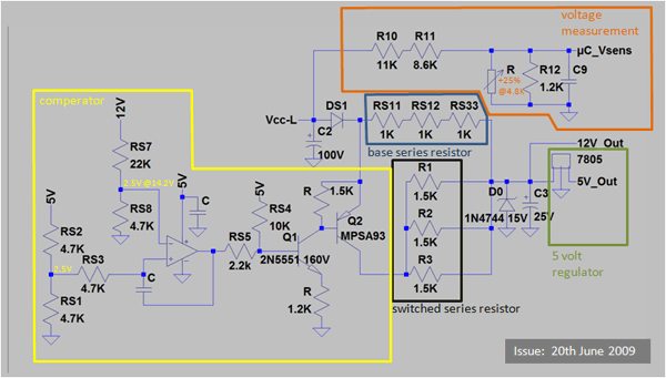
the string of RS11 -13 resistors was my issue .. removed SMD's and replaced with one large full size resistor
pVuHEl.gif

http://endless-sphere.com/forums/viewtopic.php?f=2&t=10312&hilit=methods+18fet+controller&start=240

The Wiki


lots there..but getting confusing now..http://endless-sphere.com/w/index.php/Main_Page#Electric_Bicycles
Generic Infinieon thread
maybe pics there...65 page thread..not searcng that one for you!!
http://endless-sphere.com/forums/viewtopic.php?f=2&t=10312&start=0
 
I have been searching my stash of controller photos..and I found one that looks similar.

Which is strange as I did not know I had a 12 FET controller!!

12 mosfet.jpg

If I get a chance I'll try and find it..I am thinking it maybe one in a long case that is the same size as a 18 FET case//a sensorless APM display Xlyte one that came from Electric rider with a HS motor..a mate had it and the case went live..which he shorted to a metal part of the bike frame..he bought a new one..I fixed this one. and it is now in a box somewhere.

I'll check the board number, you do the same with your board
 
Found more..guess it is an EB312?

Answer these for me;
Is the board number the same..pic 1 EB312-C1
Is the MC the same ..the multileg chip the same..pic 2
Are MOSFETS the same ...pic 4
Looking at your pic I guess yours is wired for the APM too?

View attachment 5
EB312-APM header2.jpg
EB312-APM header3.jpg
EB312-APM header4.jpg
EB312-APM header5.jpg

 
Hi Neil,
Thanks for the help, l won't be able to get the controller until later the week but will reply once I have it.
Cheers Matt
 
Took mine apart today.
The resistors drop the voltage initially down to about 40 volts
U2 the LM317 drops the voltage down to 29 volts
U1 the smaller voltage reg drop it from 29 to 5 volts
 
Thanks Neil for all your help,
I have another photo of the back of the board that I took earlier when first dismanlted after the problem started. My one is 36-48 volt digital controller wired for the APM display. The boards look identical even though you board is the 72V version? I note that I only have two resisters place across R01A, R01B & R6 . The first is wired from the top port for R01A to the bottom port on R01B and the second is across R6. looks like there is not much solder on the top port of R10A? Could be a problem.... Will have another look once I get the controller back from my father.
Just to confrim the resistors that you spoke about in last post that drop the voltage down to 40V are the surface mounted resisters at the bottom of the board below the capacitors.
photo-002.JPG
 
Not so sure if this board has SMD's that do the same job. As I said I am not a Electrical engineer. so since they are not in the same place I am nit sure..would need to attempt to trace the circuit..but if it is not identical I will find that a bit tricky.
I guess if you wanted to make yours run at a higher voltage, you would need to at lest, add one more resistor, and maybe change the Capacitors..FETS and maybe other control resistors.

From looking at, and from what I understand, looking at the circuit I posted earlier, there is two sets of resistors that drop the voltage;
the big ones, (R01A R01B R6) (R1 R2 R3 in the diagram) that take all the power/current
and some smaller SMD's (RS11 RS 12 RS33 in the circuit diagram)

not sure if or where the SMD's are on theses boards. I see two strings of SMD's on these boards, to the right of the big power resistors, on e near the edge and the other above that , just above the capacitors.could be either of these..try and compare you board with the circuit and see if you can find similarities
 
Thanks Neil,
Really apprecieate your help
I got the controller back last night and opened up. See the photos below. It’s the same board as your one with 4310 fets. I measured the resistance of the two surface mounted resistors at the bottom of the board (stamped 01C & 85B) and they were around 10 and 8.5 ohm each which matchs the correct valves of 10k & 8.25k. When powered up the first resistor dropped the voltage from 45 to 20.5, and the second down to around 2.5. The first regulator u2 cut the voltage from 2.7 to around 1.7 and the second regulator u1 cut to 1.4v.
Looks like the resistors have the correct resistance. I expect the high voltage drop is caused by high current. I'm thinking this could be caused by faulty regulator (s) (or set points ?) or some sort of short drawing a high current?
photo (2).JPG
View attachment 2
photo-004.JPG
photo-005.JPG

Cheers
Matt
 
Umm weird figures.

Well having the input of U2 at only 2.7 volts is wrong to start with from my measurements on my board. How are you measuring 2.7? Negative lead of DMM on system negative..the main battery negative.

Just looked at a data sheet for the first LM 317 that appeared on the RS website
http://docs-europe.electrocomponents.com/webdocs/0790/0900766b80790920.pdf
and minimum input voltage is 4.2 volts
Looking at the board from the top..FETS away from you, the pins on the U2 reg the LM317 are
Adjust, Output Input.

You should be getting a lot more voltage on the input pin.
 
U1 is the 5 volt regulator..that should have 5 volts or so on its output...and I seem to think the output from U@ connects to the input of U1..can't check though, my board is back in the workshop
 
Thanks Neil,
I agree, there should be 5V output from U1 and the input volate to U2 is far to low. AS thhe resitances across the SMR's are ewual to the stammepd rating, they apperar to be working correctly, therfore I think there is a higher amps flow through this circuit to bring the voltage down?
I measured the voltage between the main negative terminal on the board which is connected to the battery negative.

Cheers
Matt
 
No, I don't think the problem can be too high a current flow , must be something further up stream, causing the too large a voltage drop before U2
 
Hey..I just have been given another one of these same EB312 -C1 boards with no 5 volt..
While looking that the resistors and determining the pinout on the back I happened to leave the board turned on, while doing something else.

I came back a few minutes later, and thought I noticed somethning odd when I moved the board...Yep it was odd, the solder was melting on the back of the board at the board edge end of the two power dropper resistors.

They both measure 275 ohm and both appear to be dropping about 35 volts across each one..works out at about 0.13 amps..near enough 5 watts.

I am not going to take the other one apart today, it may be weeks before i get around to it... rebuilding a LiFePO4 pack that burnt, due to a mates shoddy wiring
 
Back
Top