
That worked out well, lots of copper and no thin sections.Finally I have some sort of battery design:
It has taken forever for me to get this far
You are using an out of date browser. It may not display this or other websites correctly.
You should upgrade or use an alternative browser.
You should upgrade or use an alternative browser.
Yamaha YZ450F
- Thread starter j bjork
- Start date
j bjork
1 MW
Thanks, it was just the top one on the first picture I had to add material on.
Otherwise there would have been a thin section, the 3 cells to the left are all parallel. So especially where they meet the 4:th cell would be a weak spot.
I cant really shake off that maybe I should go 28s11p instead of 30s10p like this is..
It is nice to be able to use the same chargers as the other bike, but less controller options
j bjork
1 MW
Alright, so now it is pretty much no turning back as I ordered the busbars.
I asked if they could include a few extra of the small square pieces that welds to the cells, so I could do some testwelds on old cells.
But they couldent understand what I wanted, after some back and forth they asked me to send a picture.
I sent this, and got the reply "those are included" and they sent a picture of a battery pack with welded busbars.
I gave up after that
j bjork
1 MW
The copper plates arrived a few days ago:
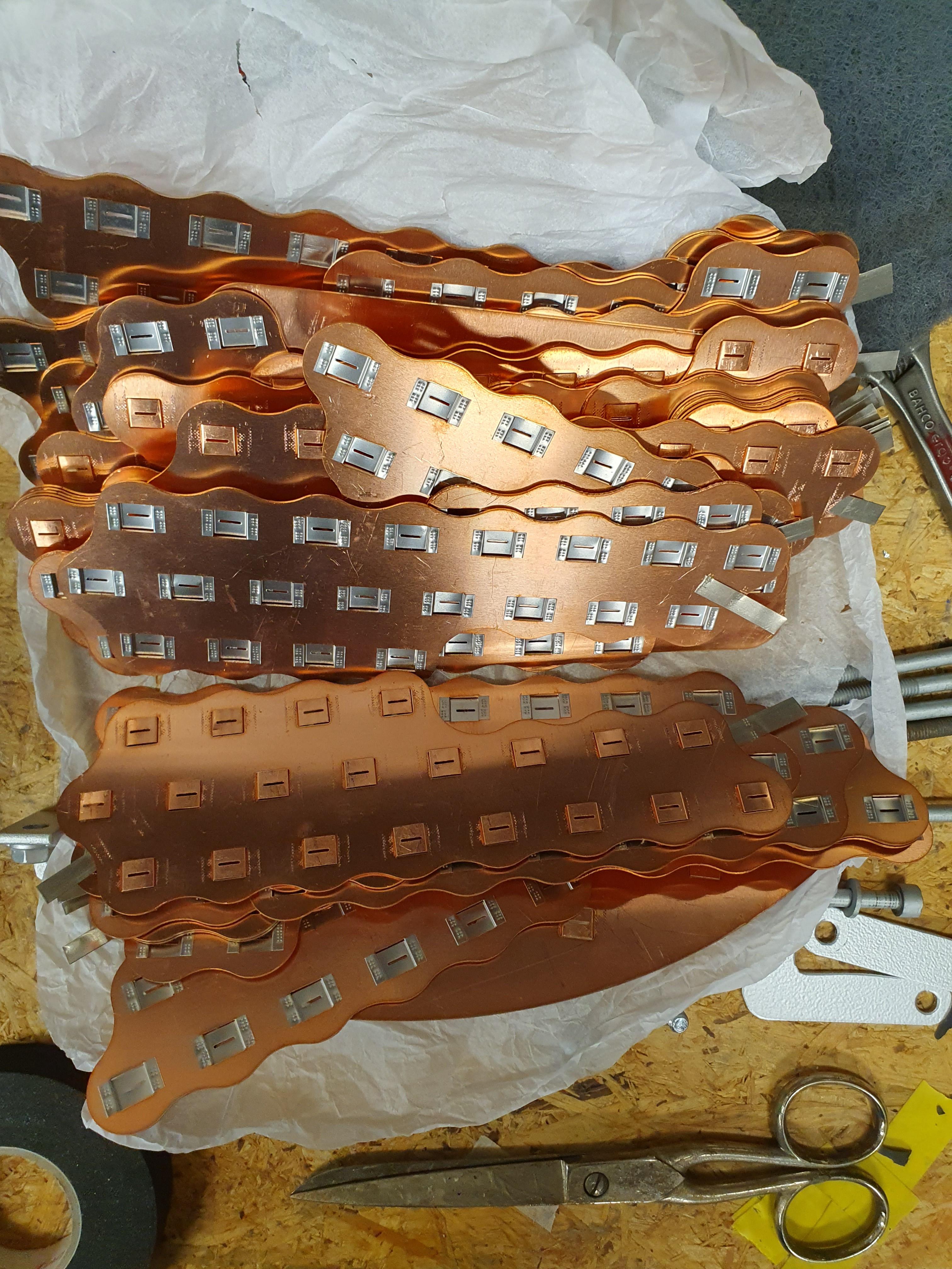
About 2kg for one battey
Maybe I should have asked for 0,5mm thick, they suggested 1mm and I didnt disagree.
As I dont have any weak spots really, 0,5mm should be more than enough I think.
My weakest is 3 parallel cells have to share a 30mm wide "passage". So now it is 30mm2, in 0,5mm it would still be 15mm2.
Can you post your listing of the product you ordered? Because it probably defines the thickness of the nickel they use. And you could just order the same thickness nickel, in separate strip form, for your test welds to find your settings.Alright, so now it is pretty much no turning back as I ordered the busbars.
I asked if they could include a few extra of the small square pieces that welds to the cells, so I could do some testwelds on old cells.
But they couldent understand what I wanted, after some back and forth they asked me to send a picture.
I sent this, and got the reply "those are included" and they sent a picture of a battery pack with welded busbars.
I gave up after that
Don't feel bad, I just put 3.6kg of copper onto my battery!About 2kg for one battey
Maybe I should have asked for 0,5mm thick, they suggested 1mm and I didnt disagree.
As I dont have any weak spots really, 0,5mm should be more than enough I think.
My weakest is 3 parallel cells have to share a 30mm wide "passage". So now it is 30mm2, in 0,5mm it would still be 15mm2.
Anyway, You'll have much less resistance with the 1mm copper, that will be nice
No need to worry about 1 or 2 kg , I have installed 120mm² copper bus bars 3mmx40mm.
Only a little bit oversized. My battery can do 800A continous.
The other option I had was 0.8x40mm which was mechanicaly to weak for me.

Only a little bit oversized.
My battery can do 800A continous.The other option I had was 0.8x40mm which was mechanicaly to weak for me.
Last edited:
j bjork
1 MW
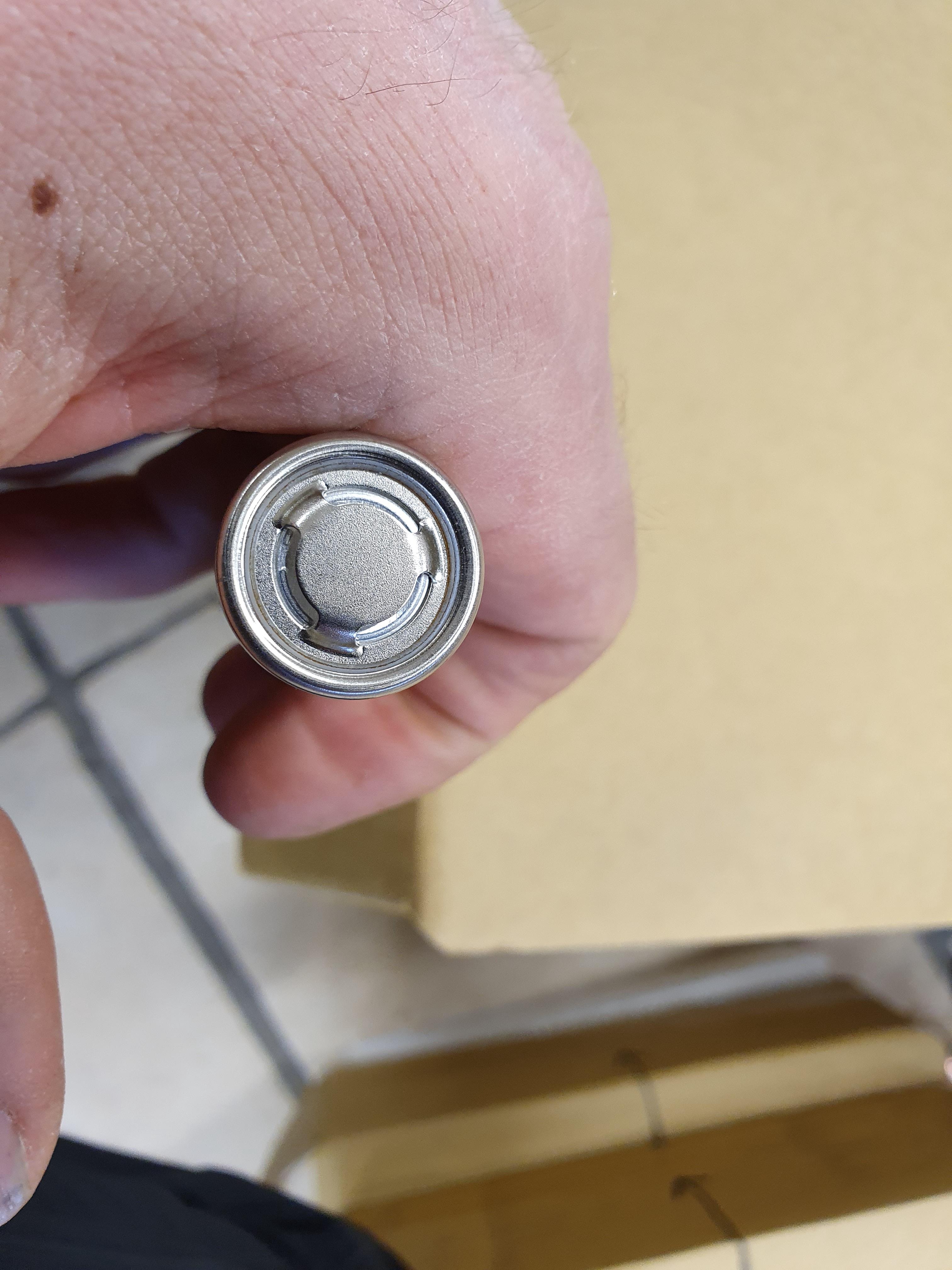
Problem is that it is not nickel, I think it is nickel plated copper. And there is a slit in the middle.Can you post your listing of the product you ordered? Because it probably defines the thickness of the nickel they use. And you could just order the same thickness nickel, in separate strip form, for your test welds to find your settings.
10p of molicell p45b, so I suppose 450A, maybe I can go a little higer for my short 2sec bursts? 500 or so.What's your anticipated peak battery current?
Oy, that'll be tricky. Keep us postedProblem is that it is not nickel, I think it is nickel plated copper. And there is a slit in the middle.
j bjork
1 MW
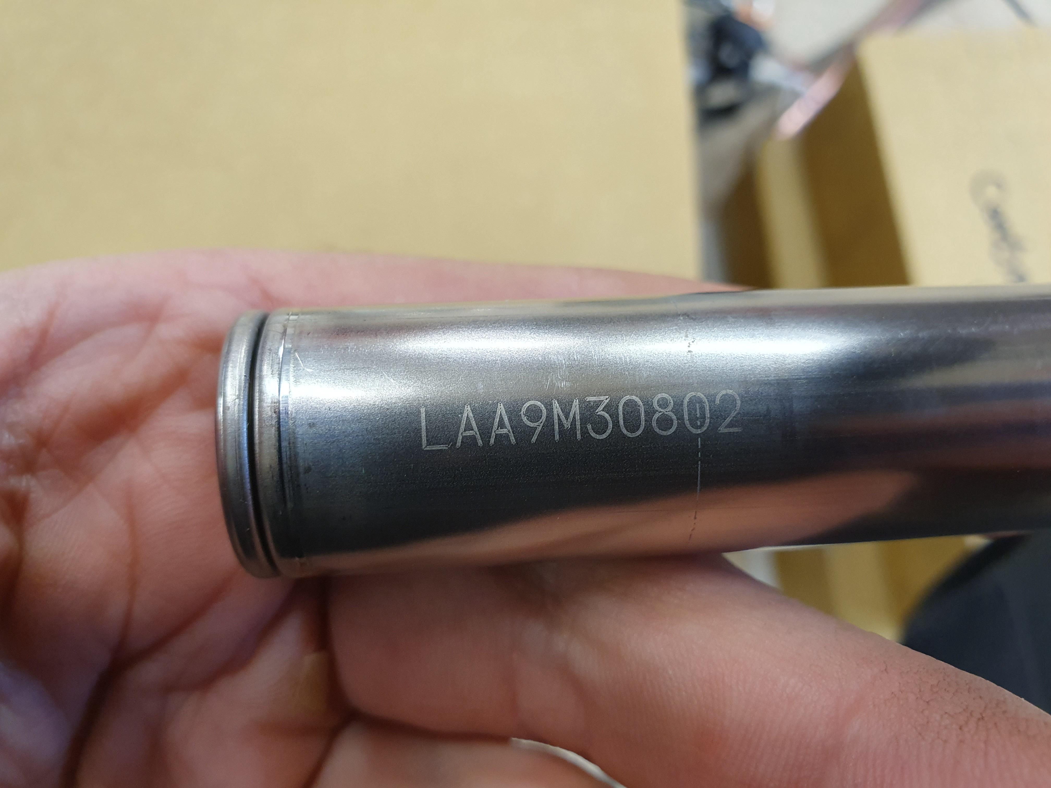
Suddenly without any warning these turned up:
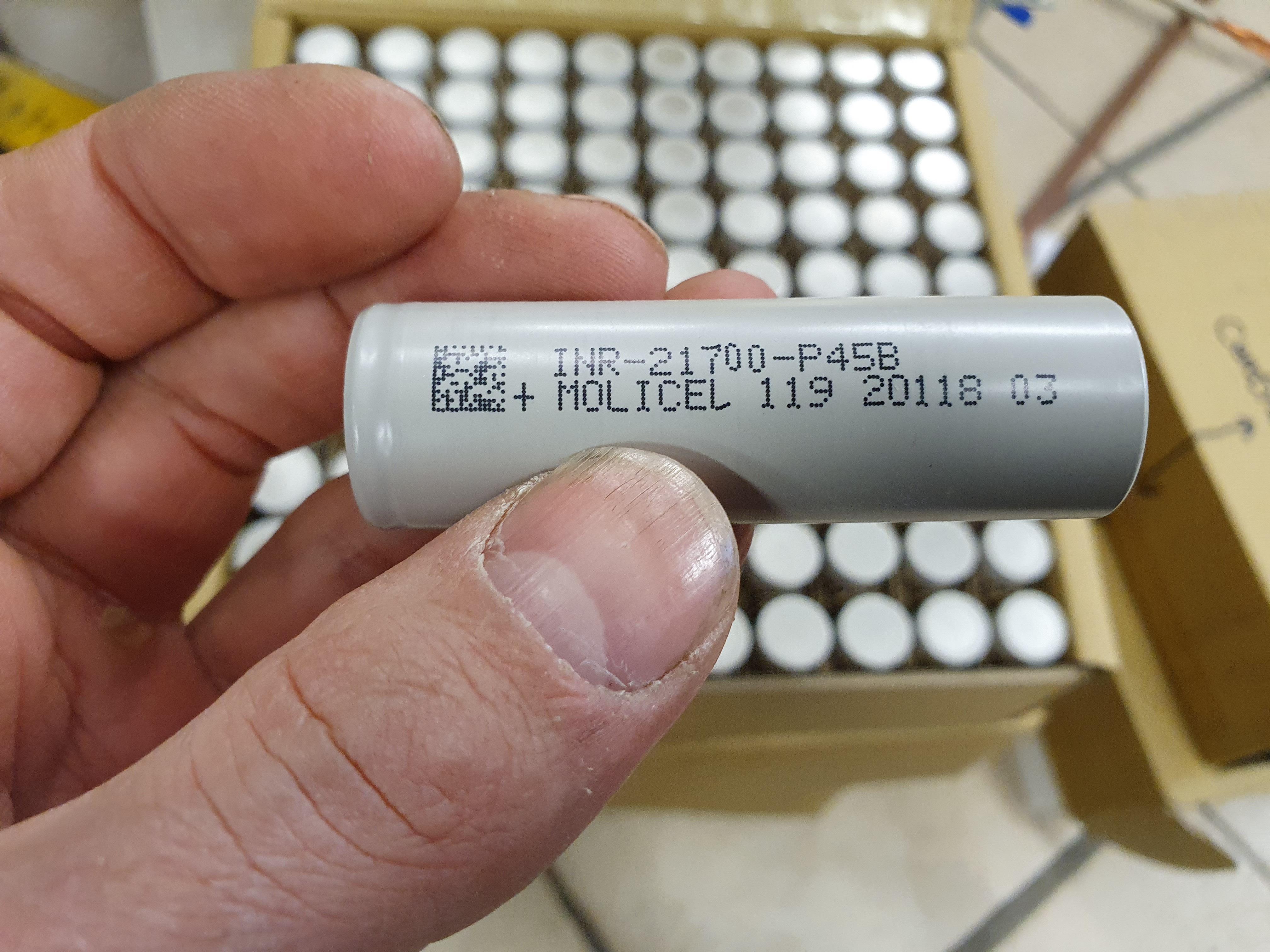
The tracking number I got still hasnt moved..
I have been chasing info about how to decipher the numbers, eventually I found this:

I suppose that means they should be manufactured 18:th January 2024?
All the cells I have looked at has the exact same numbers, not sure if that is a good or bad thing?
Under the wrap.
So, I think there are 3 possibilities here:
1: everything is fine, they are newly manufactured molicel P45B.
2: They are factory rejects, like B, C grade or something.
3: They are fake.
I think 2 are less likely as they seem to all be the same batch as they have the same numbers?
If they dont discard whole batches when they discover a problem, that might actually be kind of likely
The tracking number I got still hasnt moved..
I have been chasing info about how to decipher the numbers, eventually I found this:
I suppose that means they should be manufactured 18:th January 2024?
All the cells I have looked at has the exact same numbers, not sure if that is a good or bad thing?
Under the wrap.
So, I think there are 3 possibilities here:
1: everything is fine, they are newly manufactured molicel P45B.
2: They are factory rejects, like B, C grade or something.
3: They are fake.
I think 2 are less likely as they seem to all be the same batch as they have the same numbers?
If they dont discard whole batches when they discover a problem, that might actually be kind of likely
j bjork
1 MW
Testing batteries..
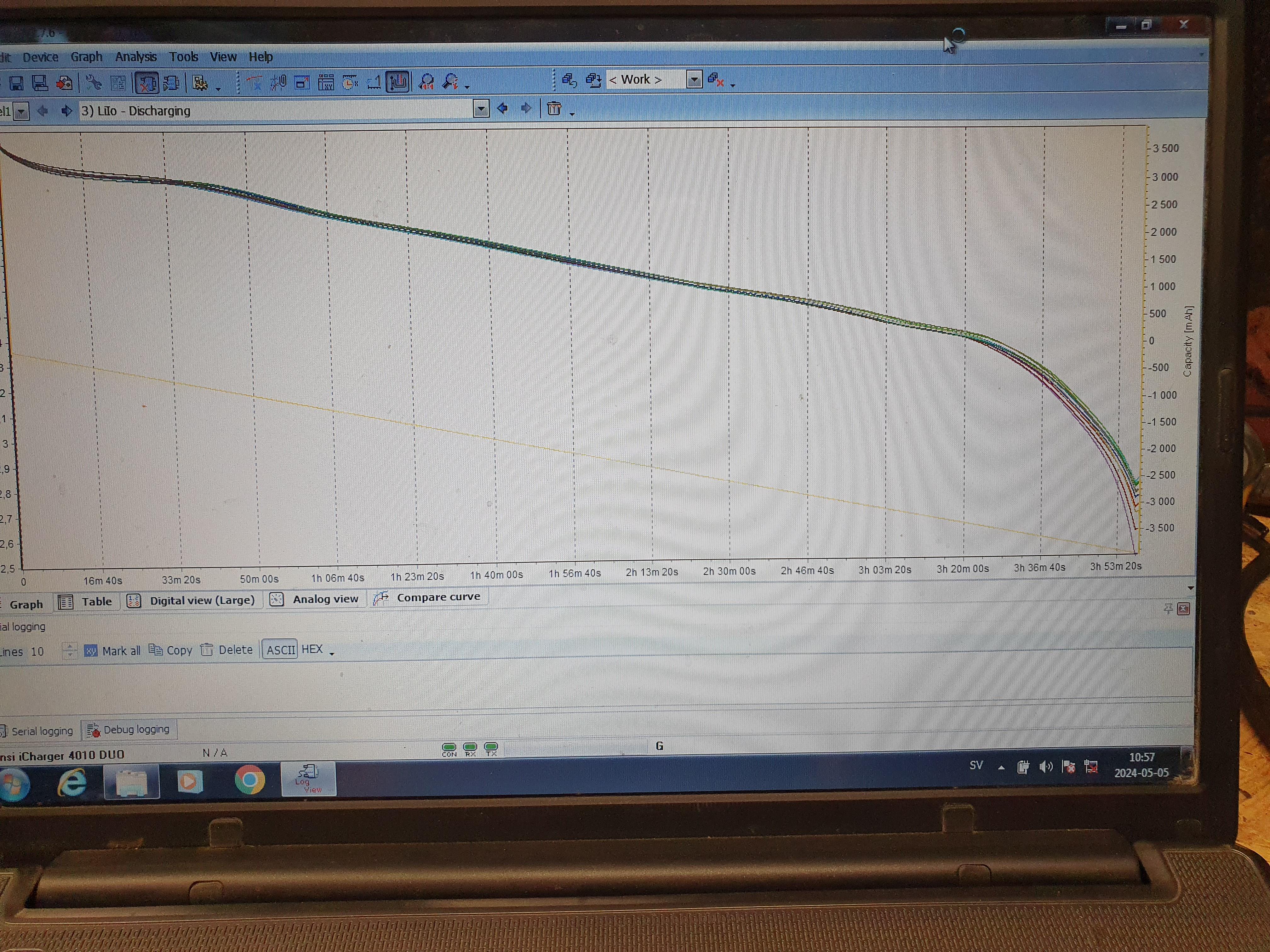
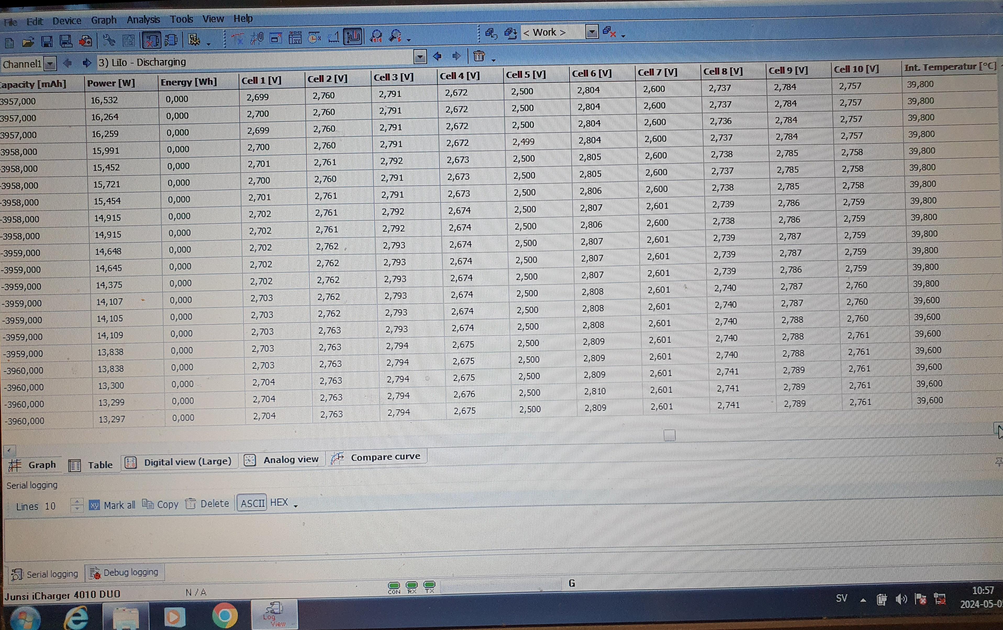
All the ones I have tried so far has ended just under 4000mah at 1A discharge.
But the test ends when one cell reach 2,5V, some cells can then be at about 2,8V.
I have seen close to 3V in one test. dont really know how much that means in mah, but I am doing a small test of the difference between the best and worst cells on the side.
I am testing 10 cells at a time, this should take about a month like this I think. I dont even want to think about testing one at a time
According to the data sheet I should be getting at least 4300mah
https://www.molicel.com/wp-content/...roduct-Data-Sheet-of-INR-21700-P45B-80109.pdf
That's disappointing... you purchased these new?According to the data sheet I should be getting at least 4300mah
Especially since you're testing at 1A discharge, you should be getting the rated 4300-4500mah at such a low discharge rate.
j bjork
1 MW
Yes, they are new.
I better make a correction, all the tests have ended at just under 4000mah.
Meaning the lowest capacity cell (of 10) in each test ended there, the others would test higher.
But still, yes I think they should end over 4300mah.
I think I should get some other cells to test for reference.
I better make a correction, all the tests have ended at just under 4000mah.
Meaning the lowest capacity cell (of 10) in each test ended there, the others would test higher.
But still, yes I think they should end over 4300mah.
I think I should get some other cells to test for reference.
Dui ni shuo de dui
100 kW
That's close enough in my opinion. I'd be more focused at the internal resistance, it says a lot more about a cell health than its capacity usually.
Did you make sure the cells were fully charged before the discharge test (I think you probably did, but better check the obvious things first). Also make sure you have excellent contact between the cell and the device that measures discharge. If you are lucky enough to have a thermal imaging camera it can help you a lot to find if there's something wrong in your setup.
Did you make sure the cells were fully charged before the discharge test (I think you probably did, but better check the obvious things first). Also make sure you have excellent contact between the cell and the device that measures discharge. If you are lucky enough to have a thermal imaging camera it can help you a lot to find if there's something wrong in your setup.
j bjork
1 MW
I do a charge (to 4,2V) and discharge cycle in each test, so I think that part should be ok.
I havent made any changes to hold times or anything like that, it is definitely possible that it is just a settings problem.
Or for that matter a calibation issue.
I think at these low currents my cell holders should be enogh, at higher currents these would surely be a problem.
I realize I dont have any picture of my test rig, I will try to get that in the evening.
I will get to internal resistance soon. My charger shows a value, it has been between 20-30mOhm, but I dont trust that to be accurate. I dont have any real tester for it, I will try to just mesure voltage drop and current.
j bjork
1 MW
Sorry, it took a little longer. I have been very busy in the evenings.
This is what the test rig looks like:

An icharger 4010 duo and simple cellholders. I noticed I am able to log both channels at the same time, but there was missing pins in one cellholder. So I was only able to set up one 10s channel, the other one is just 8s.
I have also ran a test of two of the best performing, and two of the worst performing cells in this opus charger:

They are not up there in capacity in that test either, but it looks like they are not to far apart from each other at least.
I have started a little with ir tests, but I dont have a proper test rig for that.
I tried this:

I think I need to make something better, but this is one measurement:

This is 13mOhm, but I have also measured 17mOhm:s on the same cell, and this is at 20'C and 3,7V.
This is what the test rig looks like:
An icharger 4010 duo and simple cellholders. I noticed I am able to log both channels at the same time, but there was missing pins in one cellholder. So I was only able to set up one 10s channel, the other one is just 8s.
I have also ran a test of two of the best performing, and two of the worst performing cells in this opus charger:
They are not up there in capacity in that test either, but it looks like they are not to far apart from each other at least.
I have started a little with ir tests, but I dont have a proper test rig for that.
I tried this:
I think I need to make something better, but this is one measurement:
This is 13mOhm, but I have also measured 17mOhm:s on the same cell, and this is at 20'C and 3,7V.
j bjork
1 MW
Okay, my battery holder is done.

The parts used, alu screws I had that felt ok for the job.
2 small brass nails that I soldered small wires to the edge on.
3d printed holder and sleeves for the nails.
2 ballpoint pen springs.
Another spring for one of the screws.

A little machining of the screws: a 2,5mm hole right through for the wires and a 4mm seat for the spring.

And finished
Now I just have to determine how I should test..
(Yea, Idont really know what I was thinking when I made it that long with that long spring..)
The parts used, alu screws I had that felt ok for the job.
2 small brass nails that I soldered small wires to the edge on.
3d printed holder and sleeves for the nails.
2 ballpoint pen springs.
Another spring for one of the screws.
A little machining of the screws: a 2,5mm hole right through for the wires and a 4mm seat for the spring.
And finished
Now I just have to determine how I should test..
(Yea, Idont really know what I was thinking when I made it that long with that long spring..)
j bjork
1 MW
I got a delivery a while ago:

I was in a hurry to order, as I expected it to take a long time to get it.
But it actually showed up in about a month, as it was supposed to.

All black should mean v4 as far as I know, but pin 12 is dead short to ground
On the 700/1000 v4 models it should be a "mode" input, but not cl1400 it seems.
It should be possible to use the sin/cos inputs instead according to Hackey, but it seems impossible to get him to say how..
I was in a hurry to order, as I expected it to take a long time to get it.
But it actually showed up in about a month, as it was supposed to.
All black should mean v4 as far as I know, but pin 12 is dead short to ground
On the 700/1000 v4 models it should be a "mode" input, but not cl1400 it seems.
It should be possible to use the sin/cos inputs instead according to Hackey, but it seems impossible to get him to say how..
j bjork
1 MW
Have been continuing my battery testing, eventually I got trough a 2A charge and 1A discharge test on all a little over 600 cells
I started doing some ir testing, I put on a load for 10sec and measured at the end of that. Then after the cell recovered I measured the voltage again for reference. Like this:

I have done it on about 30 cells, but got bored..
They tested about 16mOhm, that is like paja:s 10sec test I think. Not sure if it is the same test though..
I think mooch tested just under 10mOhm.
I also got a reference cell, it tests higher capacity (a little under 4400mah if I remember correct) and lower ir, 10-11mOhm.
Now I am doing a torture test, 1c (4,5A) charge and 5c (22,5A) discharge cycles:

Cant do that an the cheap cell holders, so I am using the one I made.
The cell gets 70degrees C on the discharge, so I cant go higher without cooling.
I started doing some ir testing, I put on a load for 10sec and measured at the end of that. Then after the cell recovered I measured the voltage again for reference. Like this:
I have done it on about 30 cells, but got bored..
They tested about 16mOhm, that is like paja:s 10sec test I think. Not sure if it is the same test though..
I think mooch tested just under 10mOhm.
I also got a reference cell, it tests higher capacity (a little under 4400mah if I remember correct) and lower ir, 10-11mOhm.
Now I am doing a torture test, 1c (4,5A) charge and 5c (22,5A) discharge cycles:
Cant do that an the cheap cell holders, so I am using the one I made.
The cell gets 70degrees C on the discharge, so I cant go higher without cooling.
It seems the cells aren't measuring up as per the datasheet, that is frustrating 
Once you've completed testing is your intention to get the vendor involved to try and resolve the quality issues?
They look usable but a long way off in terms of internal resistance as demonstrated by your 5C discharge test, more like a P42A.
Once you've completed testing is your intention to get the vendor involved to try and resolve the quality issues?
They look usable but a long way off in terms of internal resistance as demonstrated by your 5C discharge test, more like a P42A.
j bjork
1 MW
Yes, I think I will contact the vendor and see what they say. I dont expect much, but worth a try I think.
I think everything looks ok on the cells, so I dont think they are fake. At the moment I also think they are most likely P42a that has wrong markings. Maybe molicell ran a batch with the wrong markings that then was sold cheap or maybe was supposed to get scrapped?
I have a cell I test with 4,5A charge and 22,5A discharge, it looses about 20mAh on each cycle. It gets hot, 70-75degrees C, so I suppose it is not surprising. It seems rather stable in ir from what I see on the charger. I havent done any testing like this before, so I dont really know what is normal.
Yeah, I'm sure the cells wont be enjoying 70°CI have a cell I test with 4,5A charge and 22,5A discharge, it looses about 20mAh on each cycle. It gets hot, 70-75degrees C, so I suppose it is not surprising.

The NMC cells for my build say they are only good for 55°C.
Good luck with the vendor, hopefully it was an honest mistake and they will set you right. Supplier quality seems to be the biggest barrier to our builds and it's very hard to get accountability.
Your cell tester looks great BTW, I really like the centre hole for the 4 wire kelvin connection.
j bjork
1 MW
Suddenly something happens, I got my cellholders:

Good fitment of the cells:

I think it is the right orientation of all cells
Good fitment of the cells:
I think it is the right orientation of all cells
Dui ni shuo de dui
100 kW
Yeah it looks correct at first glance, Now its time to weld all of this!I think it is the right orientation of all cells
How were the cell holders made? CNC machining?
Similar threads
- Replies
- 5
- Views
- 1,342
- Replies
- 8
- Views
- 1,032
- Replies
- 8
- Views
- 2,017