Yamaha YZ450F

Edit: i’m curious to see how the performance turns out with your motor. I can’t believe you left QS 🥲😂
Well, when you wrote that I hadnt made the decision yet. But I thought I might as well order it,
It is no fun to do the same as everyone else anyway;)

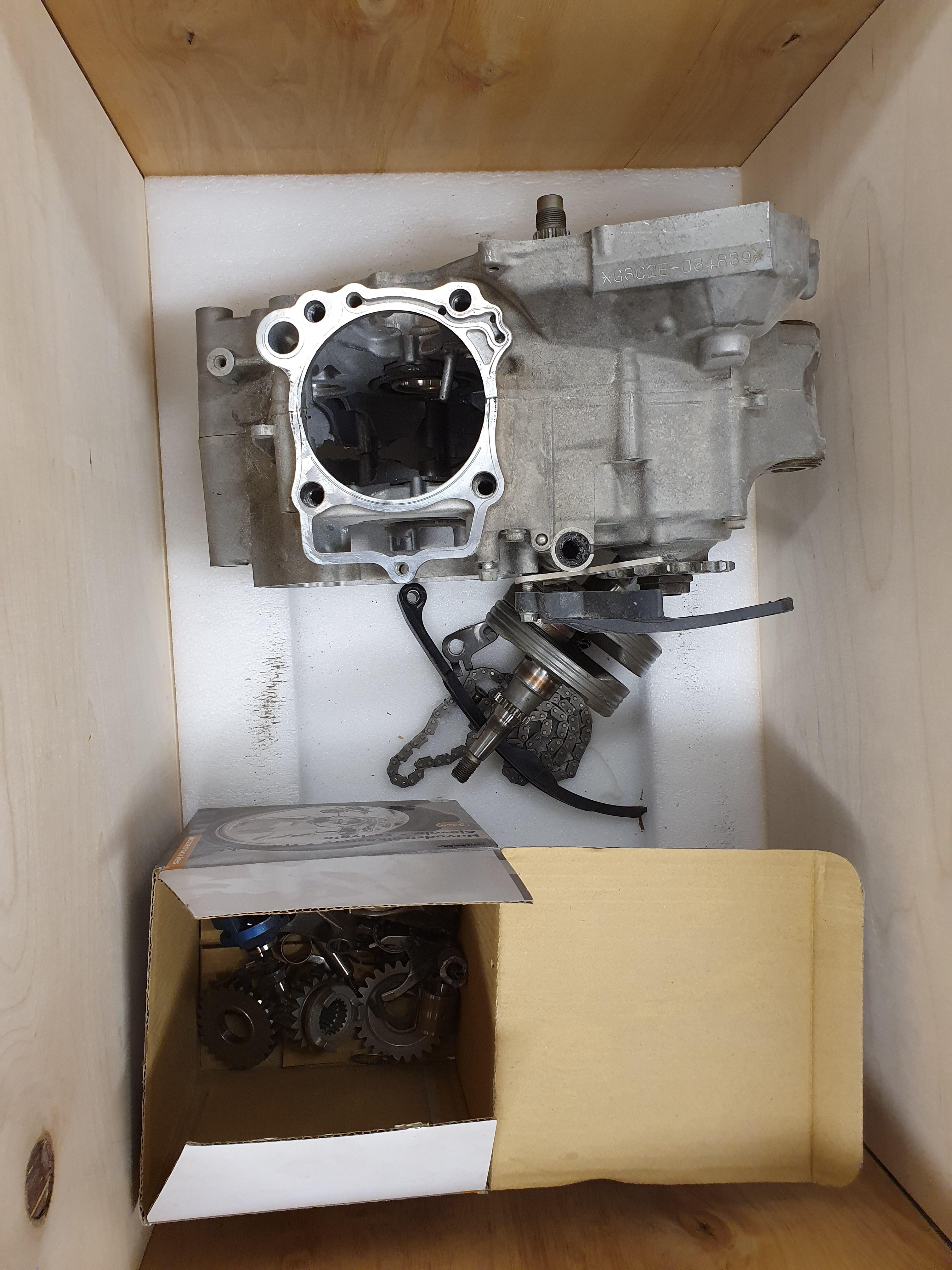
I was a little worried as it said 21kg on the parcel, and it seemed to be about right on my bathroom scale.
However, I found this inside:

Fjx3WZ2.jpg


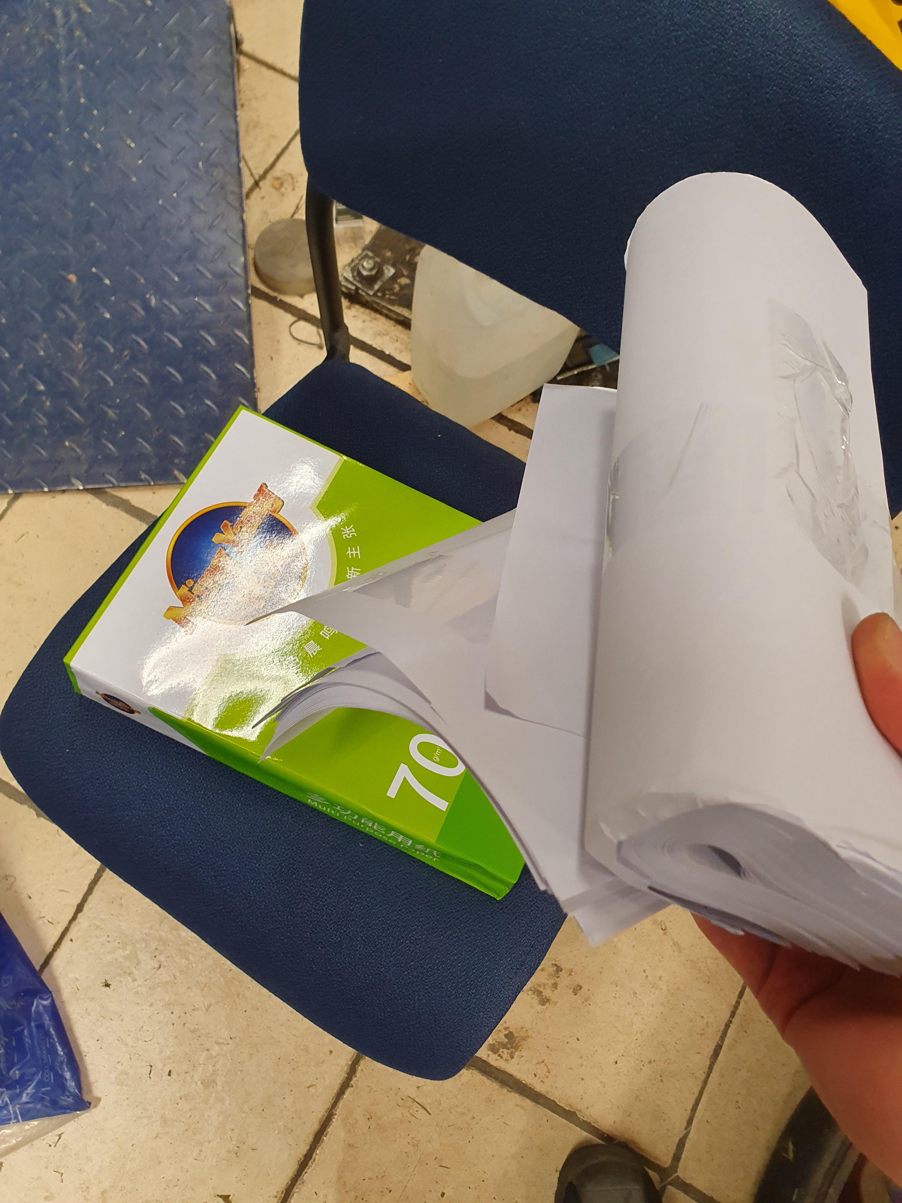
A full unopened package of printer paper, and probably more or less one more package stuffed around :oop:
I can use some paper for my printer, so it is not a bad thing I suppose:LOL:

ipg3LdM.jpg


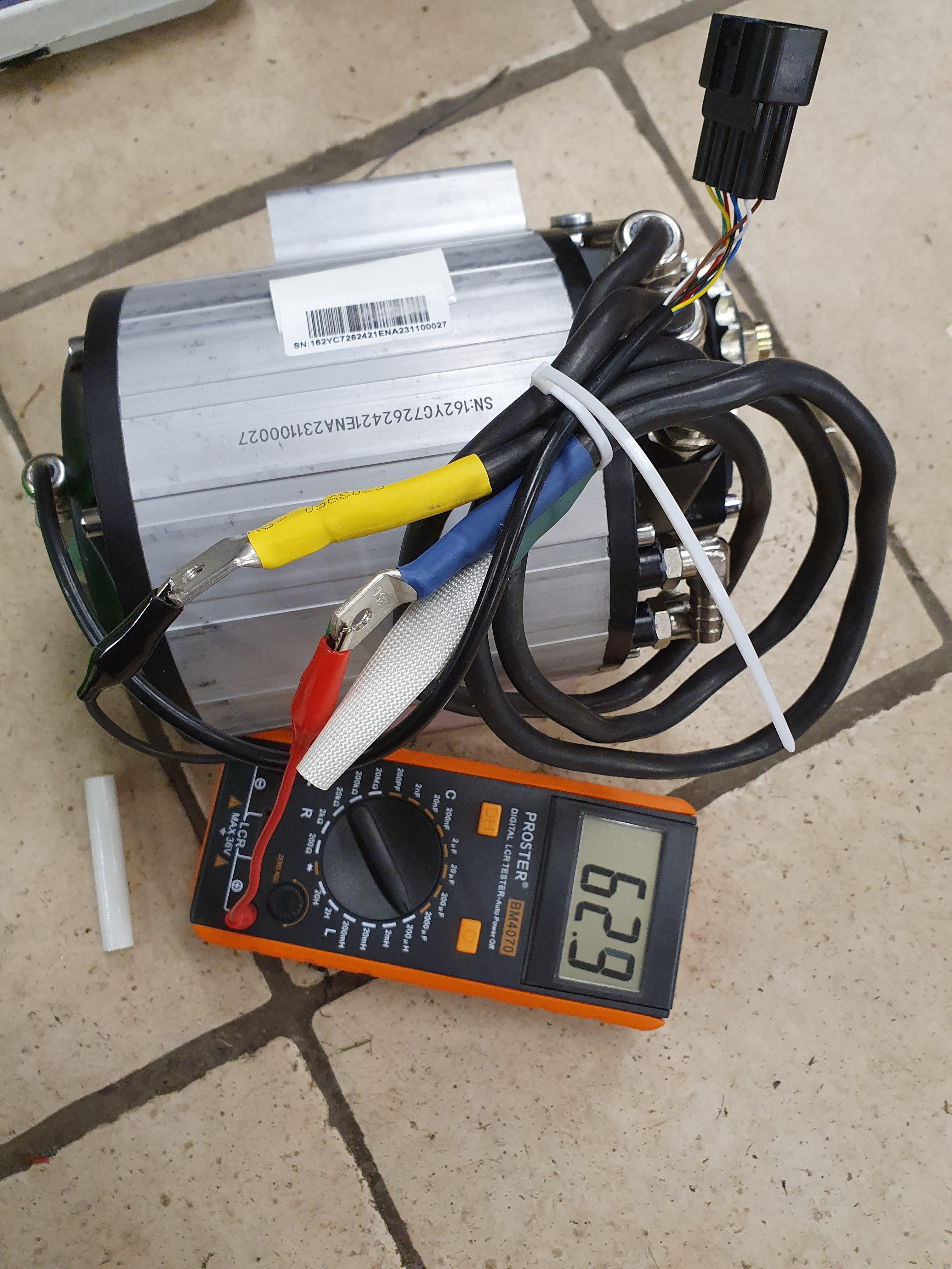
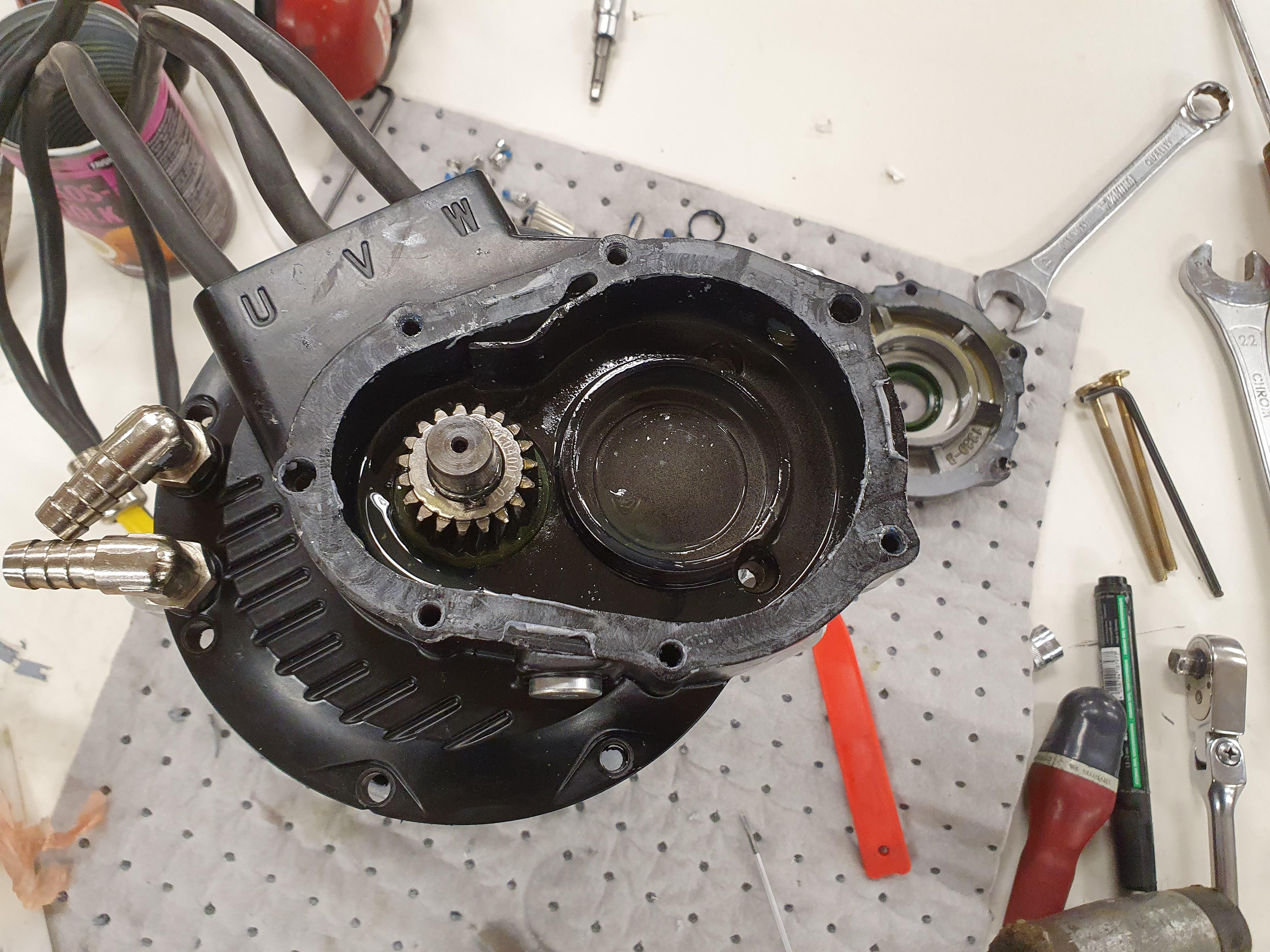
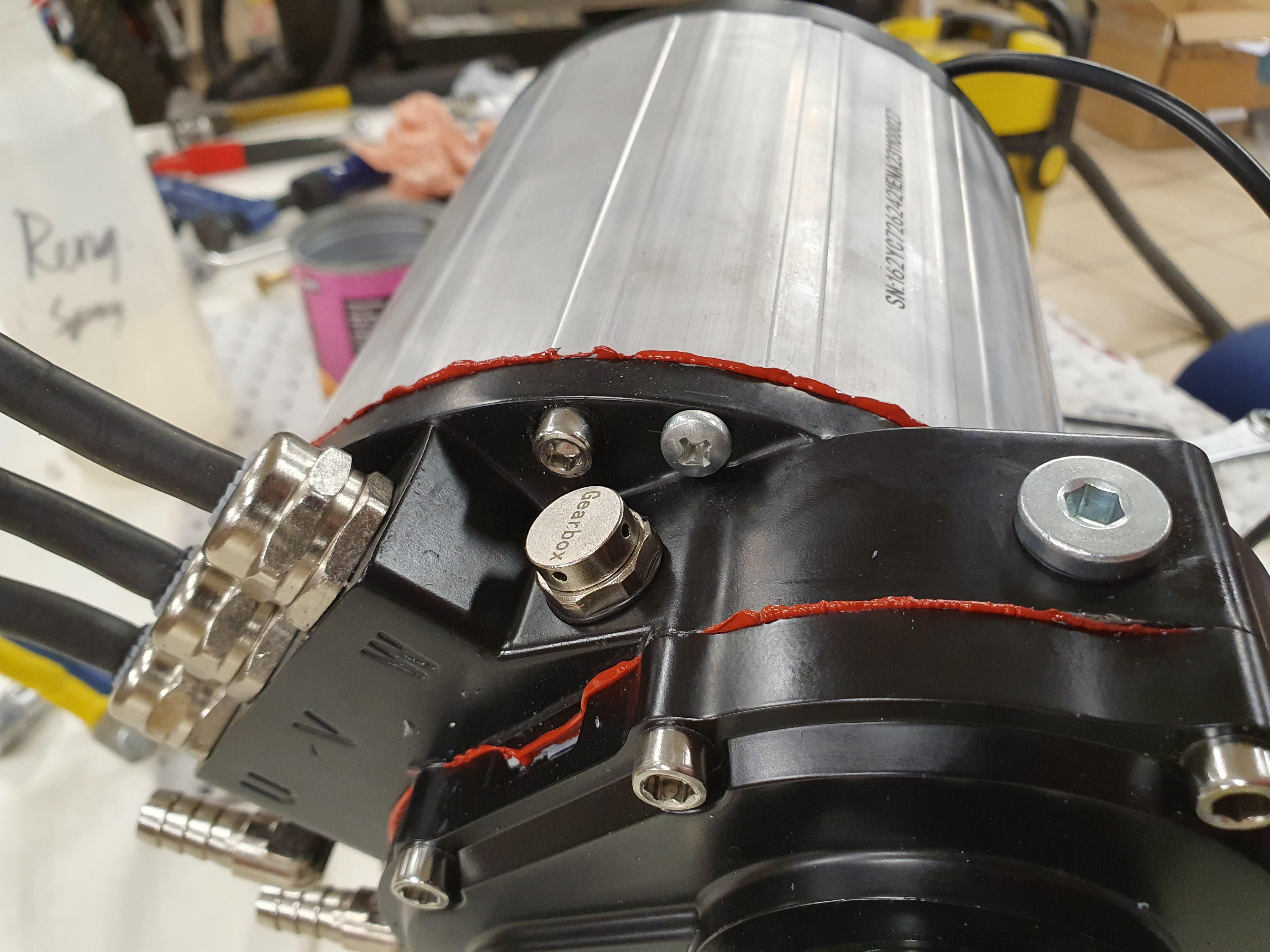
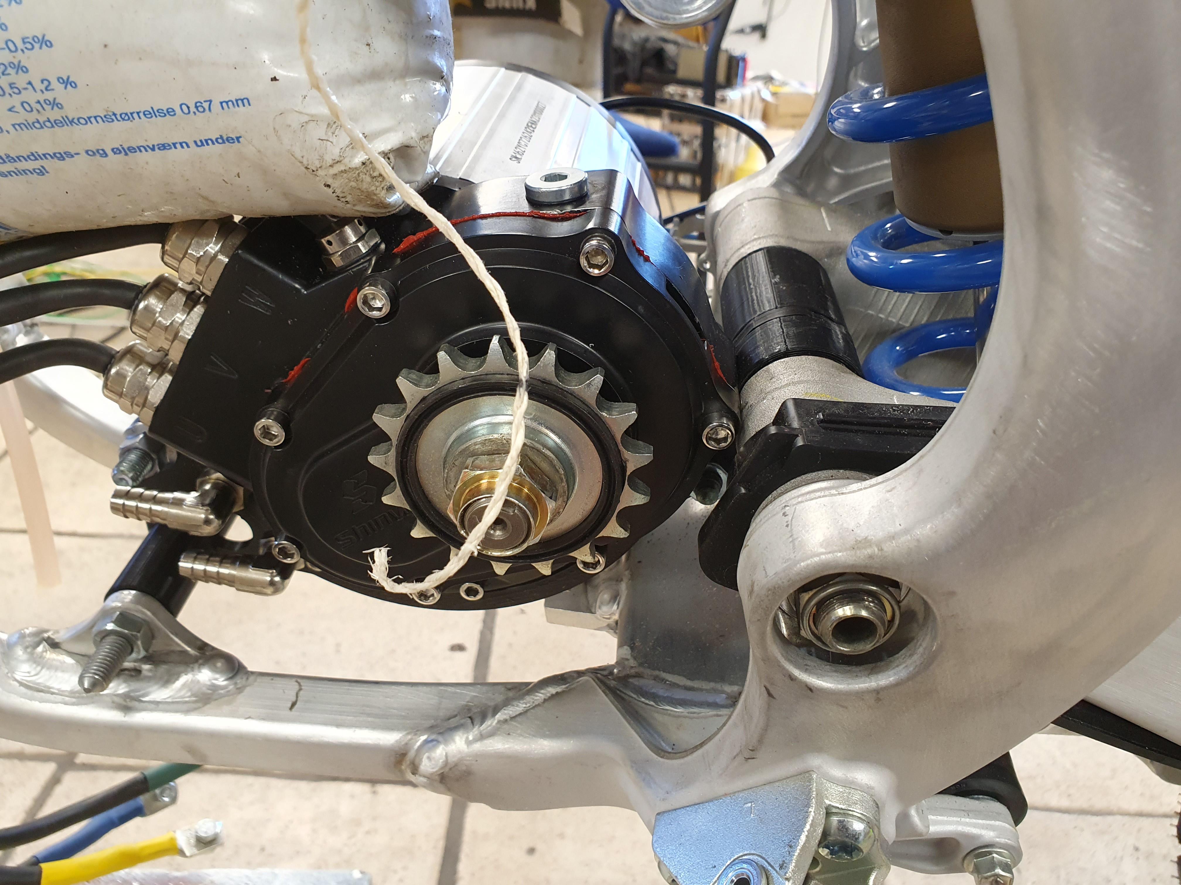
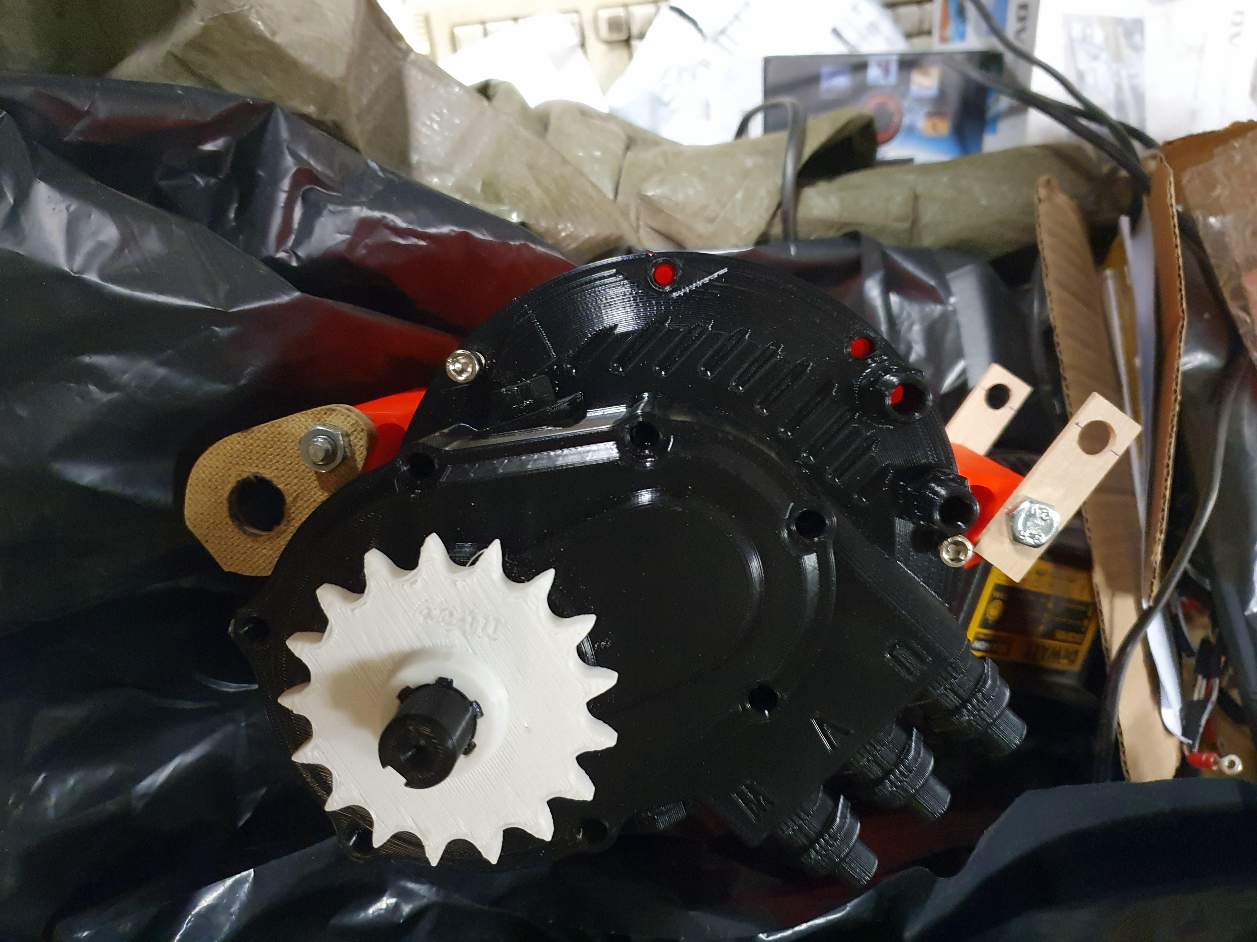
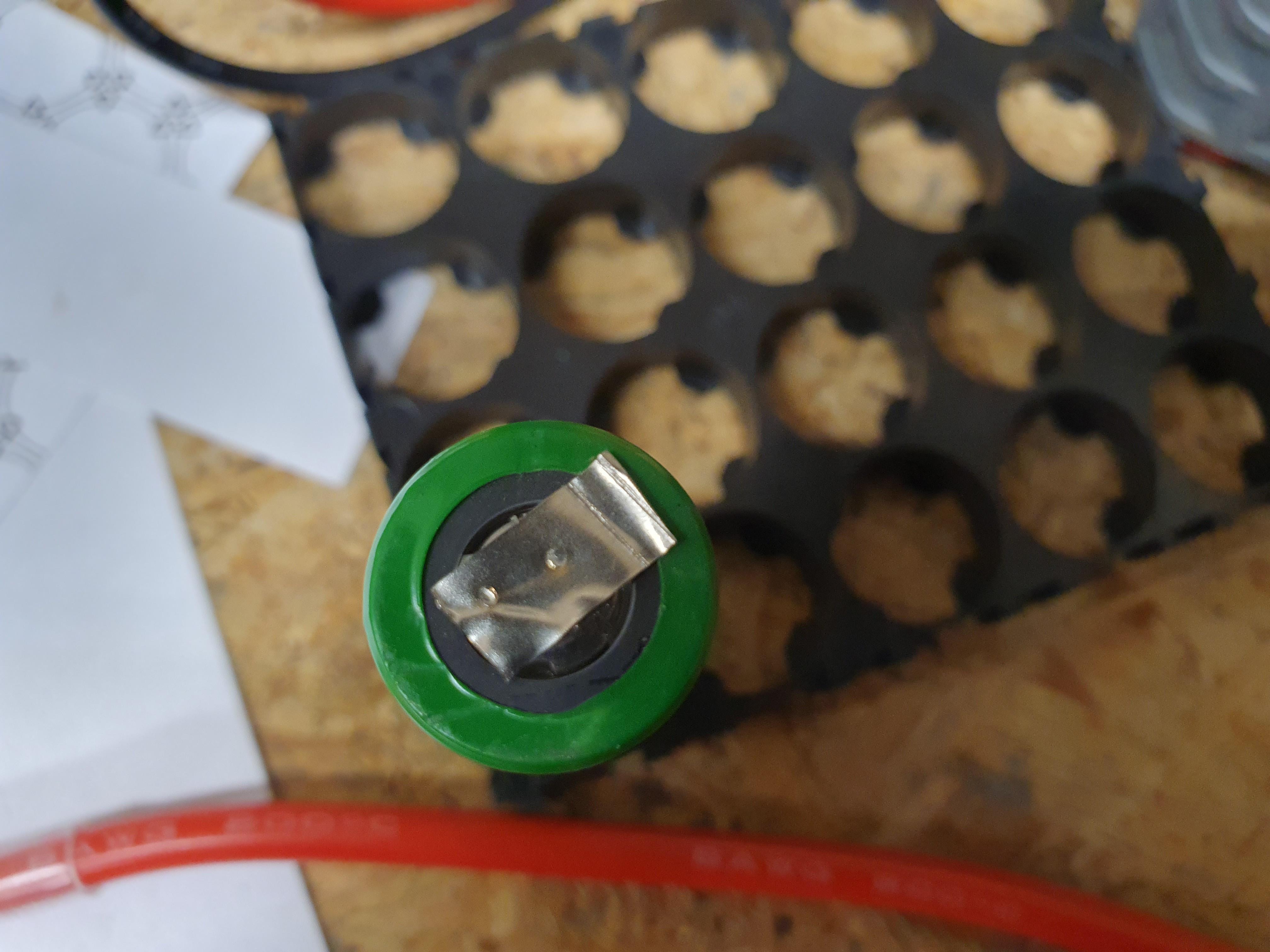
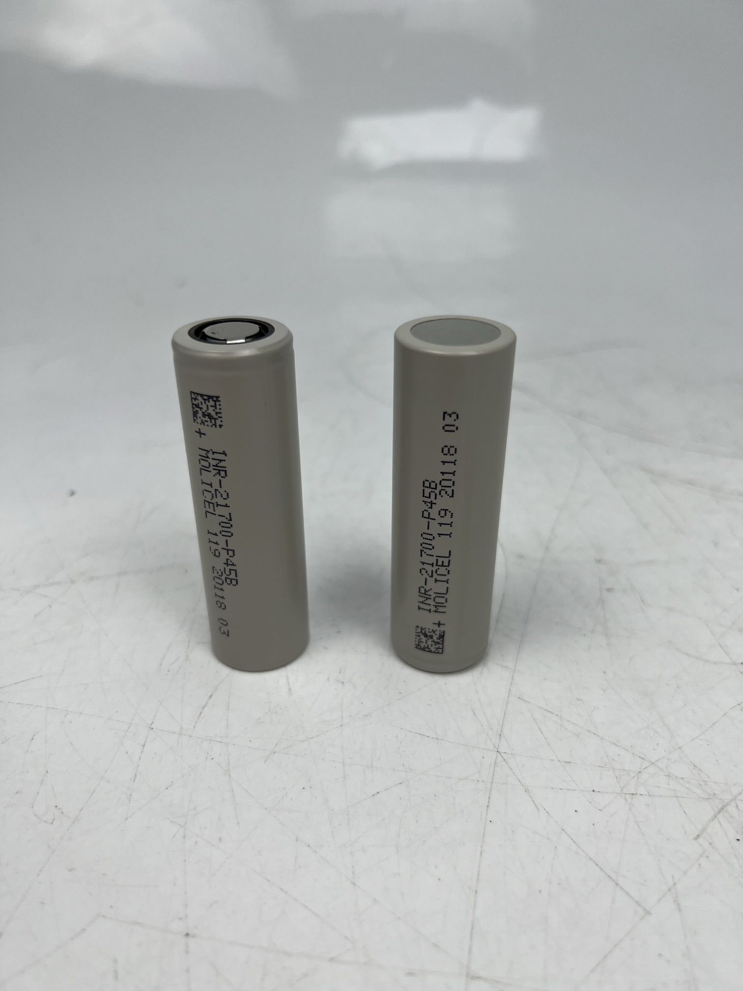
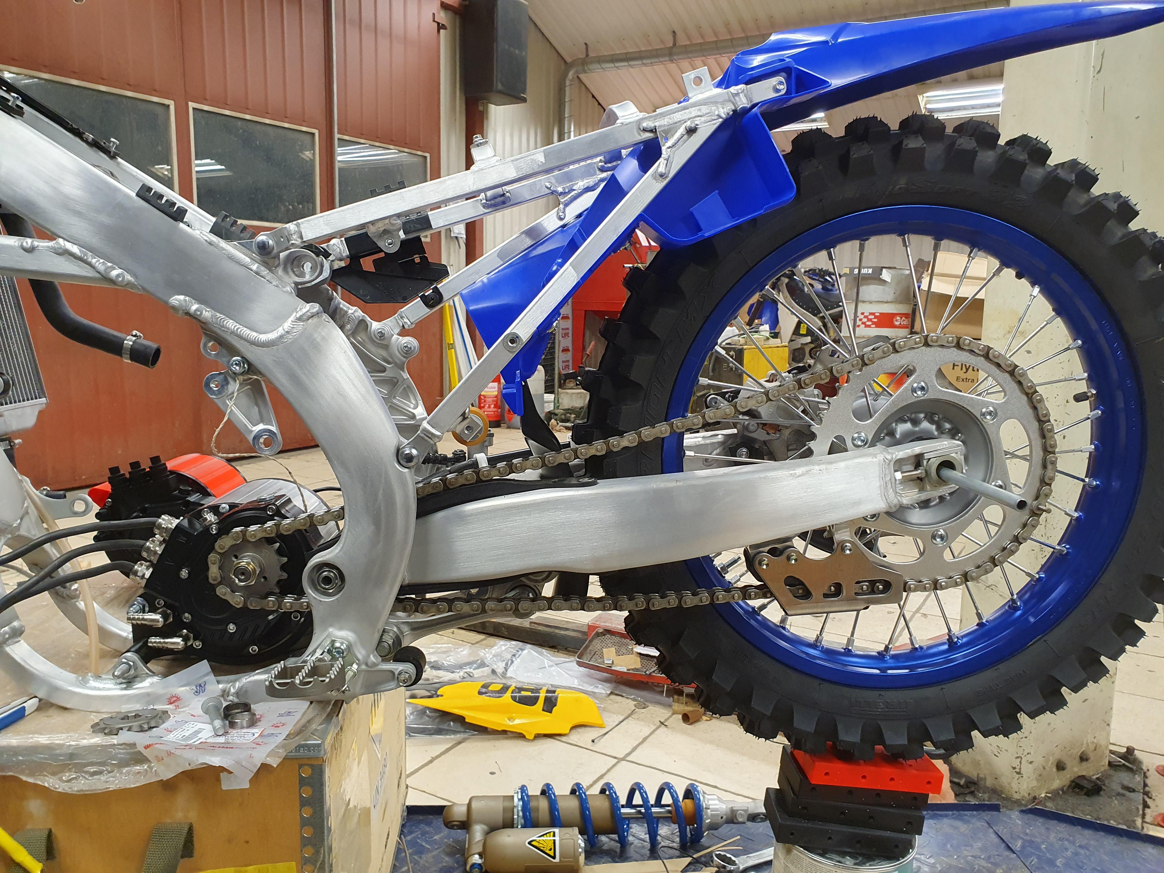
The motor itself, I checked inductance and got about 53-63uH between two phases. I suppose that means half of that in one phase, and not very salient. About the same as a qs 138 so far I think.

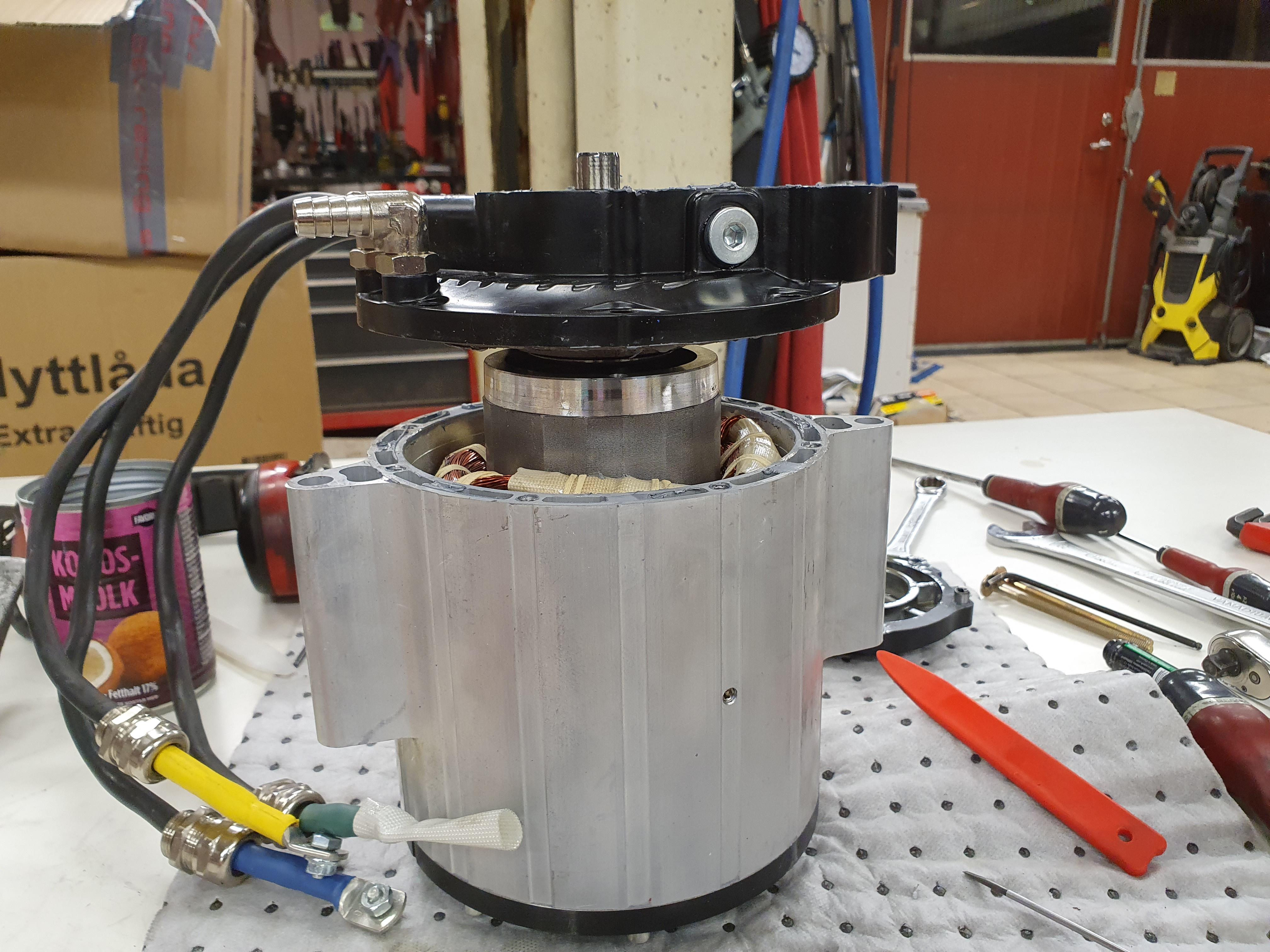
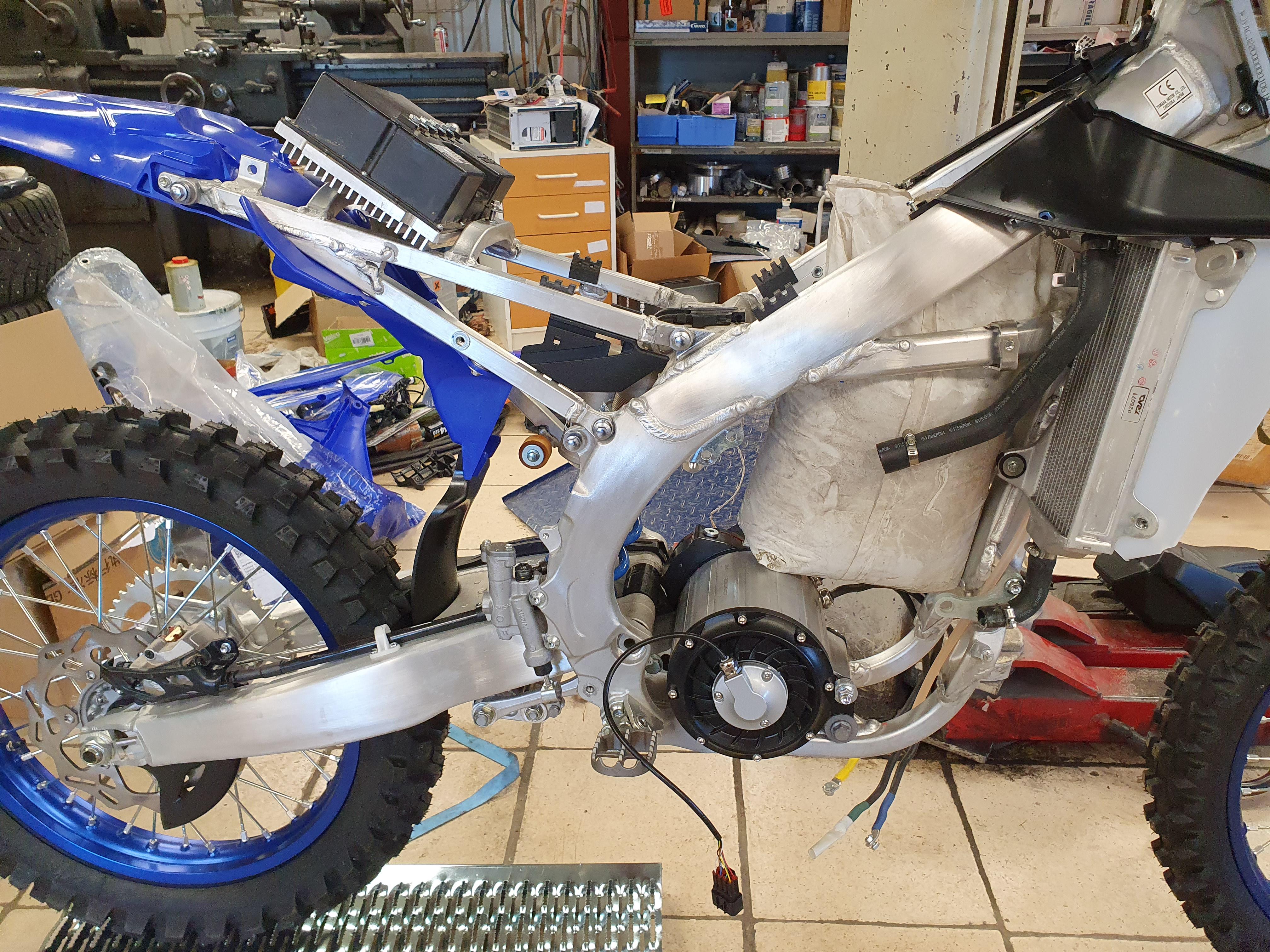
The weight was a disappointment, the specs said 12,6kg and I got about 16kg on the bathroom scale 🙁
I think the qs 138 90h is about 15kg, so pretty much in the same ballpark.
 
I tried to measure the resistance too, but hasnt been successful so far.
I got something like 2,5mohm, 5mohm and 8mohm phase to phase. I didnt have a good ampere meter and I think the winding heated up between tries. I will get back to it, and make a better measurement.

ln6WRtD.jpg


Started taking it apart to make some changes.
I didnt have any puller that I could get under the gear.
I tried to take off gear housing anyway, but I got the rotor and everything with it:

JJv8t9A.jpg


It was rather difficult to get it out and at the same time feed the phase wires trough.
I also saw that parts of the windings would rub against the rotor, and it was difficult to push them aside.
I decided to leave it like that and work in the gap.

It would have been interesting to get the rotor out and see if it is 100mm long ;)

The gearing is 19/48, so 2,526-1

9vS9Zi2.jpg


20mm wide gears, but I dont see any of the lightening holes the cad drawing had:

YNknHLI.jpg
 
As both cooling hoses will face down I expect it to be hard to get the air out.
Therefore I drilled and installed a bleed screw in the high spot:

jr91RSC.jpg


It should be possible to run a small tube from there instead if necessary.

PKeUSHk.jpg


I spun the output shaft at 350rpm x2,526=884rpm on the motor.
I got about 10,54V, so I think that should mean about 84kv.
Sounds good to me :)
 
Nice to see the insides of these things :), how did it compare price wise to the qs138 90h in the end? The gears look nice and meaty anyway
 
It ended up at about 10000sek, and it seems a watercooled qs 138 90h would end up at about 8000sek.
So 25% more, I can only hope it was worth it ;)

The oil was more like melted grease or something:

qn6jPaZ.jpg


It was very little of it too, I went with this instead:

7AZUgxK.jpg


(just because it was so thick, so I didnt want to use ordinary 80w90)
 
That "oil" looks like what I used to clean out of my deep fryer back when I used it for bacon.... (using bacon grease as the oil).
 
That "oil" looks like what I used to clean out of my deep fryer back when I used it for bacon.... (using bacon grease as the oil).
I think it can be that it is mixed with grease from the berings, and very little oil to begin with. I think it is 50ml or less.
Can I ask how wide those gears are?
20mm
 
I suppose compared to the rest of the build the difference in cost isn't too big!
I'm watching this with great interest, you'll have worn it out by the time I get to doing a build!
Are you planning on using 3shul with this?
 
Are you planning on using 3shul with this?
Probably, but I am open to suggestions.
I could build a 28s battery and change to the hallsensor pcb, then use the fardriver 961800 that I already have..

But I want to run encoder instead, and I am interested in running vesc bms and display (suggestions on displays? And bms:es too)

One option would be to change back to the fardriver on the other bike, and take that cl1400. But then I am back to 30s and a max 120v controller on that bike😫
 
Take lots of pictures of every step. This is very well done, ad it will be helpful to others!
Thank you :)

This "megan" display looks nice: Voyage Systems
But it dosent seem to have any inputs. I want a button on the handlebars to change ride mode and things like that.
I cant take out a phone and start swiping to make changes.
 
It is so annoying, it feels like I dont get anything done.

I have mounted the motor and made a new mount because it was still a little off.

95ExJFy.jpg


I think it is pretty good now, but I will test when I get the sprockets.
I ordered them about a week ago I think, but they still havent shipped them..

I ordered battery cells over two weeks ago, but they where back and forth with changes in the shipping.
Then came the Chinese new year, so now they say they will ship in the beginning of march :rolleyes:

I want to test my battery design to see how the weight balance ends up, but it feels crazy to print 300 battery cells and fill with the right amount of sand and test build the battery..
It might very well still end up that way, but for now I did some tests with a sandbag:

YKbKB9S.jpg


First I tested just the bike with the motor, 38kg both front and rear.
With the sand bag (18kg according to spec) I got 48kg both front and rear.
With the controller (about 4.5kg) over the rear wheel (as it is in the photo) I got 50kg rear and 49kg front.

As you can see the weights dont add up perfectly, I suppose my bathroom scale isnt that exact and there probably is a little height difference between front and rear wheel during the measurements. Something like 10mm or so I think.
But it looks good I think. I dont really know what I would want, but probably close to 50/50 or a little more to the rear.
 
When I started with this I went looking for the engine from the 250. I know I sold the good parts, but I was pretty sure I kept the mid parts and output shaft. I couldent find it though, so I started to fear I had thrown it away.
Then I took a wood box to put the bike on, but it felt a little heavy..
Took a look inside and there it was:

5Z31pLC.jpg


Perfect, then I could take some measurements:

slfw66Q.jpg


I cant get that close to the swing, I think I ended up about 10mm more forward.

ZHJehe8.jpg


Was able to get it in a good position after moving the front housing on the motor 90 degrees. I hope that wont be too hard in reality..
Since then I have struggled with the damn 3d cad to make a test version of the motor mounts :rolleyes:
Great to see your build!
I'm also using the YZ450F chassis and the so called Sotion motor, so cool to see what you are doing.
Question, how wide is the original yamaha engine where it fits between the swingarm?
Or how wide is the tube you 3d printed? I bought my bike without the engine...
 
Mikemx, the motor is 74mm wide where it mounts between the swingarm bearings.

yDrbcN9.jpg


My hitec motor resistance testrig ;)
I use two of the phase wires, an electric car heater element (connected in series) to get a controlled load, and a car battery.
Then I measure the current in the circuit, and the voltage drop over the motor windings:

mpYEUKA.jpg


0,305V/58,7A=0,0051959114ohm, or 5,2mOhm

So far I have 84kv
Inductance 53-63uH (between two phases)
Resistance 5,2mOhm (between two phases)

I think the inductance and resistance in one phase is half of that assuming the motor is Y connected.
Looking pretty good so far I think :)

One thing I think I have forgotten to mention, the motor hardly coggs. I can turn it by hand on the sprocket with gearing and all :unsure:
 
I got a new toy, I mean tool:

3rCg2UZ.jpg


A k-weld spotwelder. It seems to be what most people recommend.
I tested a little on an old 18650:

HE6lPGf.jpg


I had some 0,1mm nickel strip to test with.
That cell was already spotwelded before, and I preferred not to destroy good cells if possible:confused:

Then I got to think of the old, but new, totally discharged to 0v zero battery:

lYpOr9L.jpg


I remembered seeing somewhere that it was full of 26700:s, not spotwelded or anything.
There are only rubber bands and shrink tubes holding pressure on the contacts..
Seems sketchy to me, but perfect now :D

It seems I can weld 4 layers of 0,1 strip, and maybe 230-250J ?
I get between 1150-1200A with a lead acid 12v battery. I tried 2 with the same result.
Maybe I could weld thicker material if I got that up to 1500-1800 or something.
I tried a nice 12v 40Ah lifepo4 I have, but it delivered over 2000A so the welder cut out.

I tried to weld one 0,1 strip to an alu plate and a copper plate, but the welder would only reach 150J or something before it timed out. And it wasnt enough to do more than hold it in place so it didnt fall off.
 
That 3d printed case looks pretty reasonable. I've struggled to find something for ours. Is the design available somewhere?
I'd be interested in your thoughts on the lead acid battery as a power source too. I'm using 3S2P 4AH pouch cells and it doesn't seem to hold up at the higher power settings..
 
The case for the k-weld? kWeld – 3D printed housing (STL model) | keenlab
I think there were two models available, and one cut from plastic sheets.

The lead acid seem to work fine, consistent current on every weld I have done. But I have only test welded a little, not sure what happens if you do 100 welds in a row..
I am curios to test some 25Ah prismatics I have, but they are so troublesome to connect.
T4Xsgd7.jpg


I suppose 2s is to little and 4s to much?
I have 2 of these 2s1p leftovers..
 
Look at the copper nickel sandwich method before you get too deep into this. It may be helpful to you.

 
I got some front sprockets finally.
After making some sleeves for them to fit properly, it was time to check chainline:

XCU63CZ.jpg


First a measurement with the wheel in the air.

u9qiPmm.jpg


Then I took the rear shock off and put stuff under the wheel until I got it to ride height.
(About 100mm lower than it was with the wheel in the air)

4aOCOJG.jpg


And something like fully compressed. It would be better to take the spring off and see where the shock bottoms out, but I think this is good enough in this case.

I think it looks ok. The chain gets a little more tension up to a little over normal ride height, then it gets looser. Maybe I should get the sprocket slightly higher to get less rub on the upside of the slider, but then I guess the chain will get looser at the top of the stroke.
This was with 13tooth, I will test 12tooth too, and see what happens.
 
The small offset from the gear reducer makes a big difference to a: The chain tension, and b: the sprocket sizes. It looks really good.
 
Nice build(y)!


(
There is a similar project here.
I am not sure if it is successful. Power and torque versus speed. Sealing of the engine versus oil and cooling etc. ...
)
Thank you :)
Oh, that sure was different..
Interesting build, but I think it will be more like a fun test project than a good dirtbike.
I think those motors are really high voltage, like 600v or something. It would probably need rewinding to give decent performance on low voltage.
 
Back
Top