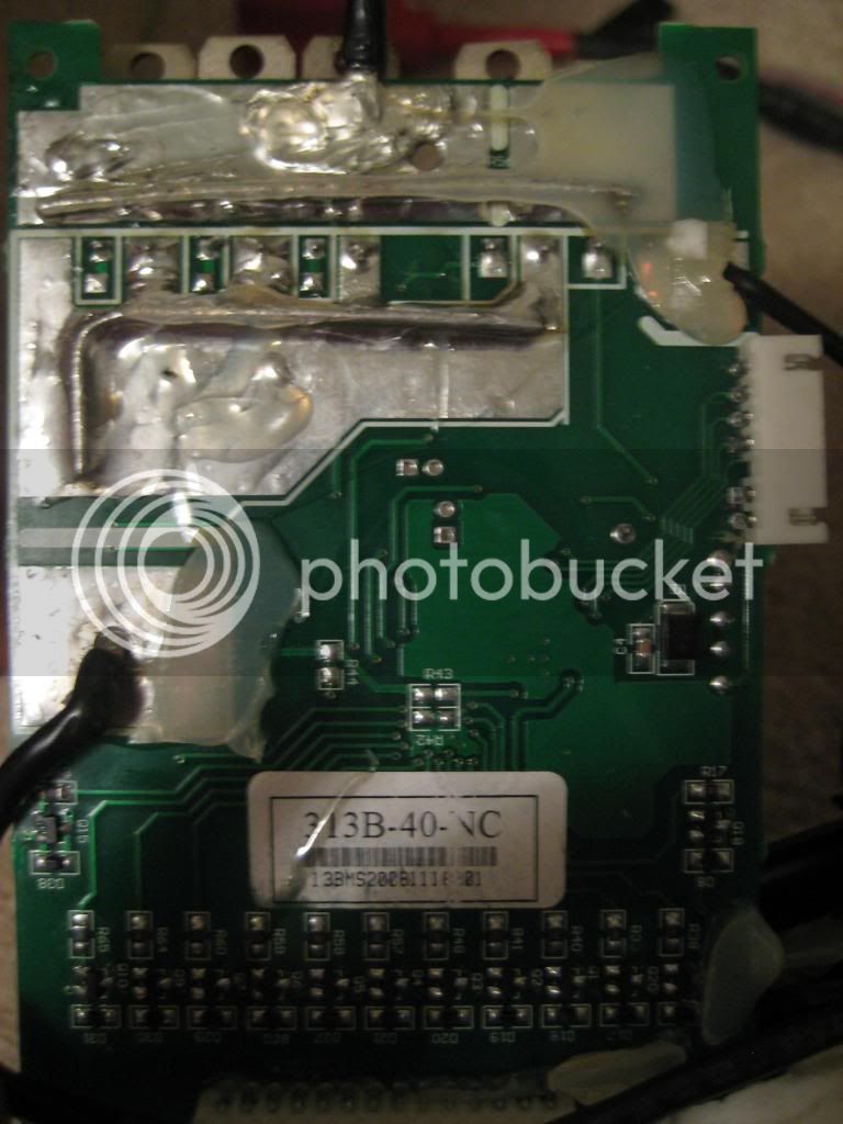
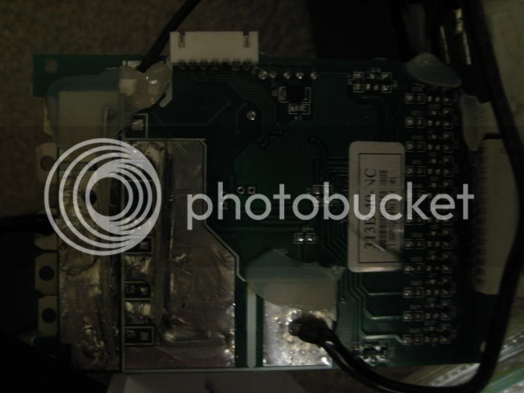
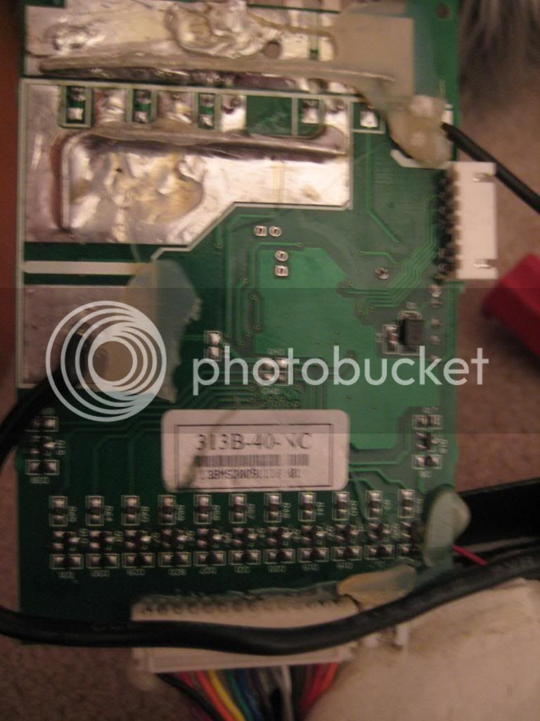
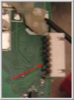
that 47.6V on the red wire is what drives the microprocessor. the wide flat ground plane with those 5 through holes in a T crossing is how the processor makes the ground connection i think and it seems to connect in the corner where it say IC1.
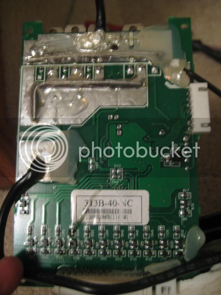
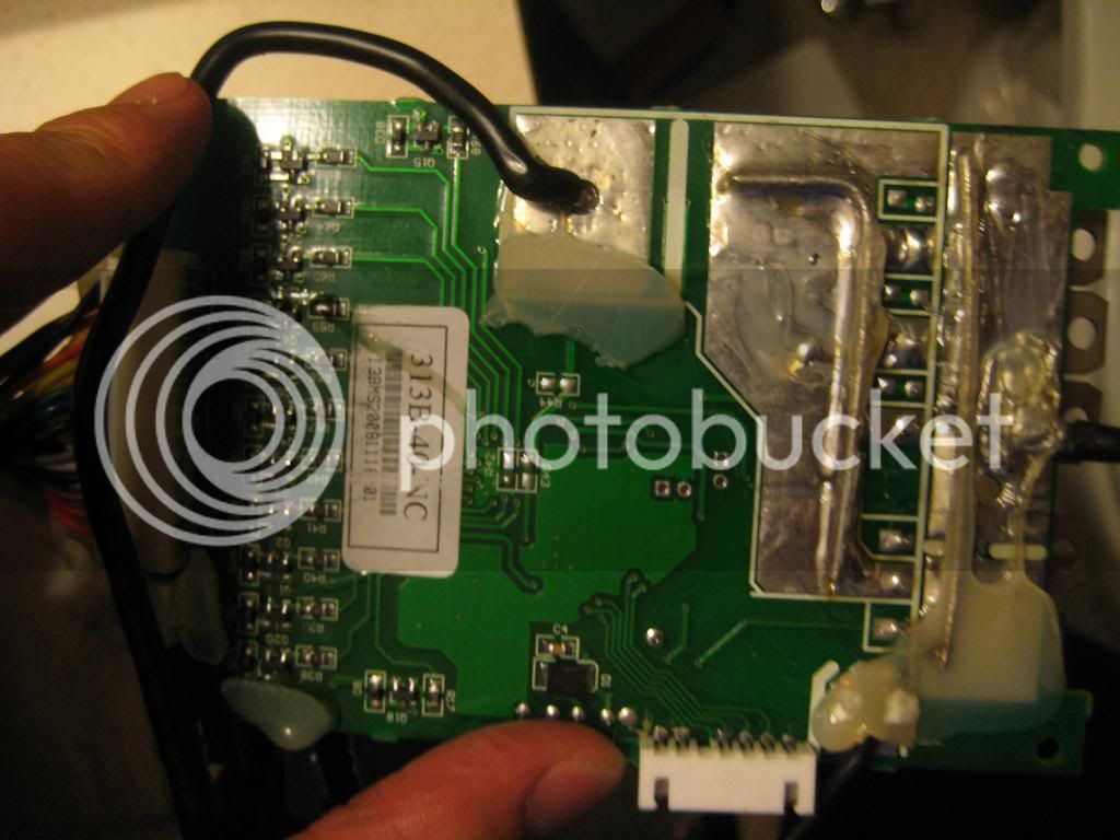
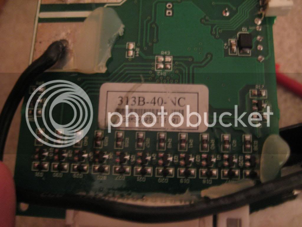
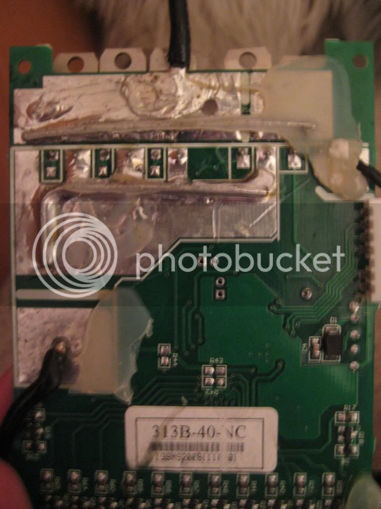
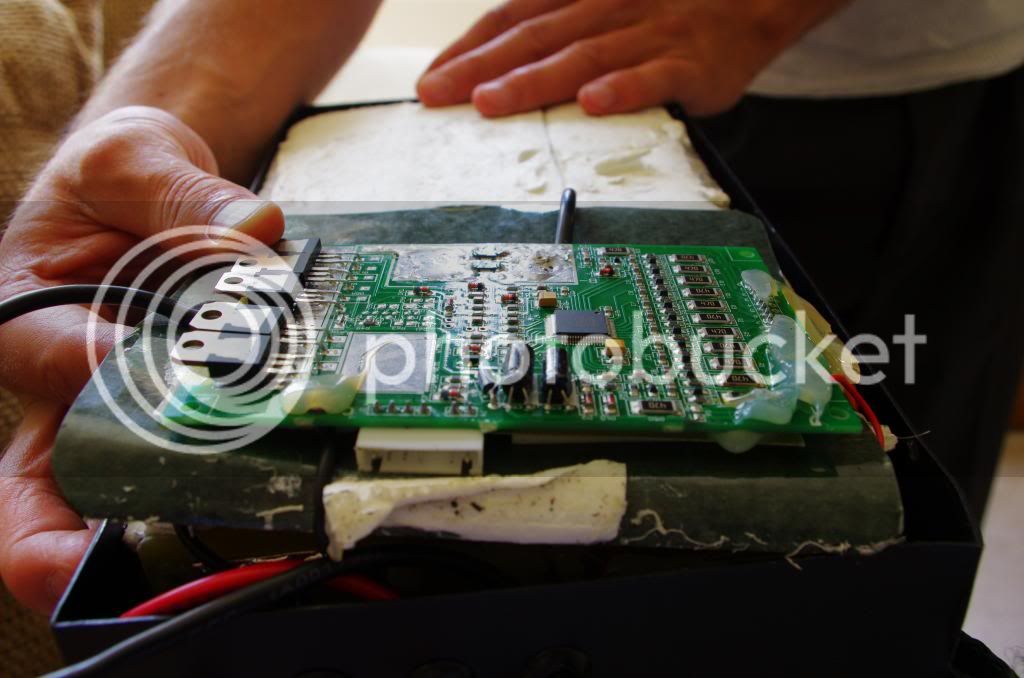
your last picture shows the shunt transistors on the underside that the microprocessor turns on to divert the charging current around the cell as the cell fills up with charge. you can see the shunt resistors on the front side and the transistor is connected to it by a through hole in the pcb.
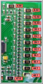
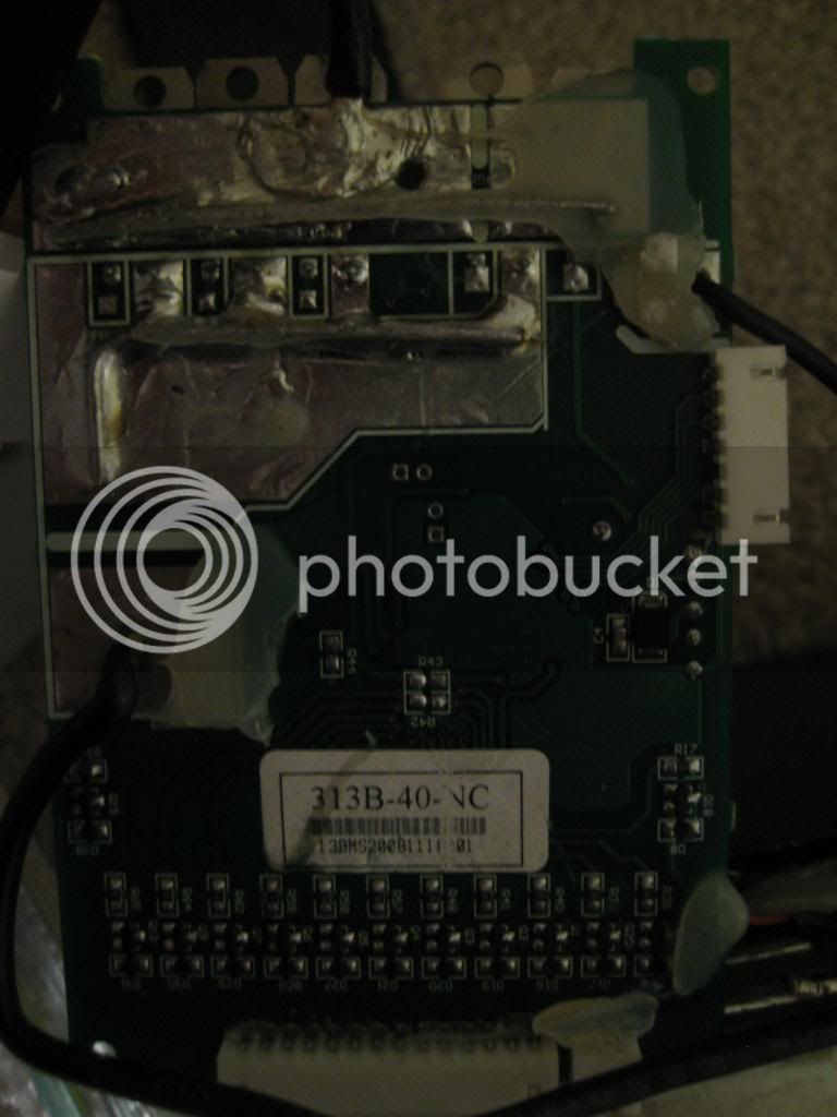
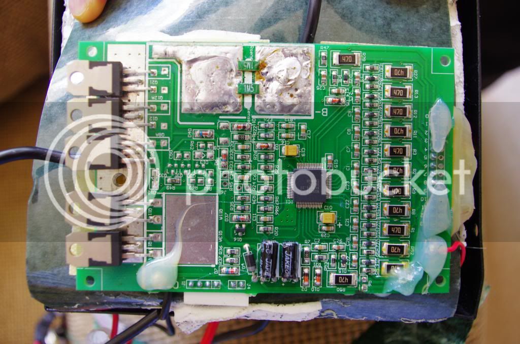
the processor monitors the voltage through those traces on the front side that connect the traces running from the sense wire plug up to the top of the shunt resistor, the ones that say 470, 47 ohms.
the R50 is the top shunt resistor and you should find the final pack voltage of 47.6V, just like the red wire since the current for the processor comes from the top of the top cell, except it is not carried on the sense wire because that would affect the voltage measurement the processor makes of each cell on the sense wire.
so there is the possibility that the BMS does not work because that connection from the red wire to the processor is open. on the BMSs i have seen with the O2 micro processor there is s fuse in the circuit from that red wire to the processor and it has a TVS, transient voltage suppressor diode, in line to blow open the fuse if the battery is connected in reverse to the BMS. so that was why i said you should see if you can follow the trace from that red wire to the processor and measure to see if that 47.6V gets to the processor. i cannot see a TVS and fuse there however.
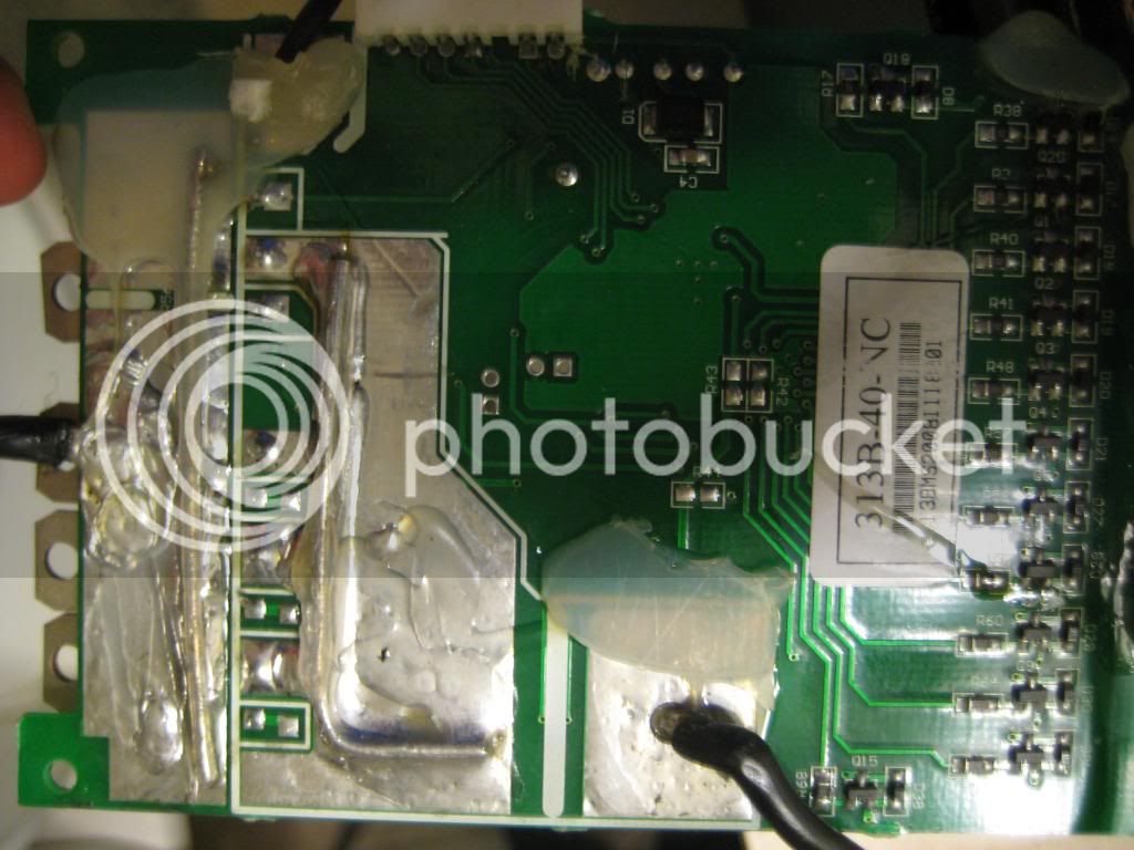
the mosfets over on the side are in two parts. the two on the bottom are for the charging and the three at the top are for discharging.
a mosfet has three legs. when you look at it from the front side, the legs from left to right are gate, drain, source. your mosfets are upside down so when looking at that picture with the mosfets on the left side of the board, the top leg is the gate, the middle leg is the drain and bottom leg is the source.
you can test those mosfets with your diode tester on the voltmeter. there is a 'body diode' between the source leg and the drain because of the way the semiconductor is manufactured. if the mosfet is damaged then that body diode is disrupted and you can tell that by measuring the body diode with the diode tester of your voltmeter.
you will have to disconnect the red wire from the BMS to evaluate the mosfets. if there is voltage on the mosfets while you test them it makes the meter very unhappy and it can die.
set the dial to the diode on the meter. put the red probe on the source leg, the bottom leg in your picture, and put the black probe on the drain. you should see a reading around 400-550mV for the forward bias of the body diode. reverse the probes and put the black probe on the source leg and the red probe on the drain leg in the middle and you should see open circuit for the reverse bias of the body diode. the meter will read off scale, open circuit, if they are functional. since the mosfets are tied in parallel you only have to test one in each set to evaluate them since they all are tied together through the legs.
but we need to determine if the last cell #13 is actually making voltage too. if each of the cells is 4v and there are 12 of them then that gets you the 47.6V and if there were 13 with 4V each then the voltage would be about 52V but you did not measure that so measure on each side of R50 to see if you can find 52V. if not then i suspect your problem is a shorted 13th channel and that is why we only see 47.6V on the red wire. if that is the case then the BMS would shut off for LVC on channel #13.

 I measured the cell voltages via the "470" resistors. They are as follow: