"Zephyr" - Finally, the "v4" Fechter/Goodrum/Hecker BMS...

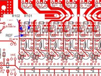
I get that the circuit must somehow think the cell is too high. Would I hook up the power supply across the circuit like it was a battery at 2.85 volts (like my cell 1 is currently?) And which ones are the divider resistors?I don't have a schematic that shows shows R101 and R102. Sorry for all the questions
 
Divider Resistors.jpg

The divider resistors are pointed out in the diagram above. Use an ohmmeter to double check their values (disconnected from pack). These should be around 73.2K and 120K assuming you built the Lipo version. Values measured in circuit may be off a bit due to other components.

You could also measure resistance (in both directions) on the legs of the BD136 and look for shorts. It should normally behave like two diodes connected at the base.

Yes, a current limited power supply that can simulate a single cell is best for testing. If not available, a regular power supply with a resistor or light bulb in series to limit the current will work. If the resistors check out OK, then apply power and measure the REF point against the negative supply wire. This should be around 2.5v.
 
The divider resistors are fine (I'm using LiFePO4 btw). Measuring from the negative to REF point gave a 2.5 volt reading on both trouble circuits when hooked up to the CC power supply. Both shunts, when hooked up to the power supply, didn't turn on until ~3.60 volts, unlike what I'm getting when I hook up to the pack.

Initially I thought the BD136's were giving different readings but I had forgot to unconnect the leads from the power supplies (that were off) which was throwing off the readings. They seem to read fine.

Why would the circuit behave differently with a power supply? I even hooked two power supplies up at once to simulate cell 1 at 2.85v and cell 2 at 3.35 volts, and neither lit up until the 3.6v mark.
 
After tinkering with the power supply hooked up more, I noticed something. The power supply won't go above 3.6 volts and if I turn the voltage dial to the right (increase) after this point the voltage starts to decrease, while the current starts to increase. And if I turn the dial left (decrease voltage), the voltage will actually increase until a point where it kicks out and goes to zero current. I thought this meant something until I tested it on other circuits and different power supplies and found the same effect, which I assume is just a normal function of the BMS.

I took a video just to help explain.
[youtube]EDGia6WeHSM[/youtube]

Still can't find anything different. The FAN431's seem fine, but the pads of one of them saw a lot of heat. I'm tempted to just replace everything on those two circuits except the resistors, cause this is the only thing standing between me riding my bike finally!
 
Sounds almost like it's oscillating. Got an oscilloscope?

Oscillation could happen if the 47uF cap is bad.
 
Before I added the 47uF capacitor, it could sometimes oscillate, which caused all sorts of problems and behaved somewhat like you described where the voltage would vary depending on load. It would be obvious looking at any of the signals with a scope if it was oscillating.

Your circuit almost behaves like there's a conductive path somewhere it's not supposed to be. You might try cleaning the board with flux remover. The real good stuff is like solvent (nasty). Alcohol and a toothbrush sort of works depending on the flux. Either that or a tiny solder bridge between traces, sometimes hard to see.
 
I did use rosin-core solder and never removed any flux; it was my first time really soldering so I probably used a little more than necessary especially on the early channels. I'll try removing some flux and double checking for solder bridges. Could a conductive path have formed spontaneously or during use? Cause it worked during my initial testing.

I'll try this and see how it goes.
 
Sometimes flux residue will pick up moisture from the air and become conductive over time. That part of the circuit is very sensitive so even a high resistance path would cause problems.
 
fechter said:
Sometimes flux residue will pick up moisture from the air and become conductive over time. That part of the circuit is very sensitive so even a high resistance path would cause problems.

Fechter, any tips for a coating that can help prevent that? Something just to spray on?
 
marcexec said:
fechter said:
Sometimes flux residue will pick up moisture from the air and become conductive over time. That part of the circuit is very sensitive so even a high resistance path would cause problems.

Fechter, any tips for a coating that can help prevent that? Something just to spray on?
I use flux remover but some flux is water soluble so just figure out what you can do to clean it. Then I have some silicon conformal coating that is like a clear coat to protect from oxidization and debris. Works great.
 
Arlo1 said:
marcexec said:
fechter said:
Sometimes flux residue will pick up moisture from the air and become conductive over time. That part of the circuit is very sensitive so even a high resistance path would cause problems.

Fechter, any tips for a coating that can help prevent that? Something just to spray on?
I use flux remover but some flux is water soluble so just figure out what you can do to clean it. Then I have some silicon conformal coating that is like a clear coat to protect from oxidization and debris. Works great.

Thanks Arlo. Any preferred product? Spray or brush on?
How about thermal conductivity - e.g the big resistors on the Zephyr to stay on topic - would you cover them completely?
 
Typically once the board is clean from flux you give it a light coating with the conformal coating. I think my stuff is from MG chemicals. You just need to keep it away from any connectors that you will need to conduct when you connect things to them.

If the board is designed right the resistors should not get hot enough to matter if they have a coating on them.
 
Coating shouldn't hurt the big resistors, but they're pretty immune to conductive paths. Around the 431 and the divider resistors is the sensitive area.

You really need to clean off all the flux before coating. I found some stuff at Radio Shack that works very well for cleaning. Comes in a spray can with a brush on the head that's pretty effective. I wish I knew what the solvent was. Alcohol is not as good but works with some mechanical scrubbing.
 
The solder paste I used is a water based flux so I can wash the boards in water and remove the flux but you must dry it very well after the best is to heat it a little to ~150 deg F for a while to get all moisture out after.

When I use my solder iron I use this stuff to remove the flux.
http://www.mgchemicals.com/products/solder/flux-removers/flux-remover-for-pc-boards-4140/
 
I tried removing the flux with 90% isopropyl alcohol and q-tips/toothbrush and it seemed to work alright. I did see some areas that visually seemed like they could be a high resistance path.

I hooked the BMS tap wires back up (without the main pack power wires) and thought I had fixed the problem - voltage was present across all of the cell banks and no LED's were lit. But upon making the main pack connection, the two problem circuits (and another I found on the back, also a little lower voltage than the others at 3.27 volts) lit up brightly as before. The only connection I had to make to get this behavior was the main pack positive connector. As soon as this was connected or disconnected (everything else was hooked up) the LED's would turn on/off.

I'm more confused now - beforehand, I think the LED's would come on with just the tap wires connected and no main power, but I'm not 100% sure.

Why would powering up the control circuit cause those problem shunt LED's to turn on? I thought that the LED's were isolated - controlled and powered by the cells they are connected to (evidently, as they're draining those cells slowly). Would it have to do with the octocoupler thingies? That's the only connection I can see to the control circuit.
 
That is strange. The Control circuit should not affect the cell circuits.
Let me think about that one. You might try checking the ref voltages on the lit cells.
 
After looking at it, it seems about the only way powering the control circuit could affect the cell circuits is if there is a conductive path across the opto coupler. It's nearly impossible for the optocoupler to fail in a way that would allow this. Maybe a lightning strike might do it. I suggest try cleaning the board between the rows of pins on the optocouplers.

Seems like the solder you used has some really nasty flux.

As mentioned before, alcohol is only so-so for cleaning. Real flux remover spray is more effective. The rosin stuff gets hard when it cools off and doesn't dissolve easily. Mechanical scraping helps (tooth brush or brass wire brush). Sometimes I use the end of a small screwdriver to scrape the hard stuff off.
 
Spent over an hour scrubbing and trying to deflux the opto couplers. They look visibly clear of flux. Hooked the first 16 cells up, with main pack connections, just to test (2nd half of pack not connected via tap wires) and thought I had fixed it cause the LED's didn't turn on and the main LED was red for once, not yellow/orange.

Put everything back together, hooked the tap wires up, then hooked the main power wires up and uttered several profanities cause the same LED's were back on.

I have the BMS tap wires split into two different plugs. When I have the main pack wires connected, and the bottom half of the tap wires, the LED's are off, but when I connect the top half they turn on.
 
Cells 1,2, and 29 have their shunt LED's lit up brightly. Cell 3 and 4 seem faintly lit up but may be trailing off from cell 1 and 2 being lit up? I have no idea. Total cell count is 30. I have two boards, one has the first 16 cells and the other has the last 14. That's how my BMS tap wires are split as well.
 
There's definitely something goofy going on.

How about trying to post a picture of the setup or a diagram showing how the pack is connected to the boards and how the two boards are connected to each other. It might give me a clue. A close-up pic of cell circuits 1 + 2 might help too.

It should also be possible to run the board without the pack attached if you can adjust the charger voltage so the shunts just barely light up. In this mode you can measure the individual cell circuits to see their set points.
 

Link to picture of board schematic, wouldn't fit normally cause it's a PDF.


Two 54 volt adjustable Meanwell power supplies on the left (adjustable up to 117 volts or so), the BMS boards and cables on the boards.


Tap wires for the two halves of the pack.


Jumper wires for HVC/LVC lines and 16th/17th cell taps.

Hope this helps, let me know if anything needs clarifying.
 
It looks correct. About the only thing I would try is to make a connection from the main pack terminals to the corresponding tap wires on the boards. This would be one on the negative side of cell #1 and one on the positive side of cell #30. Make the main pack connection before making the sensing wire connections.

As a test, you could also try just connecting the main + and - pack wires to the boards without attaching the sense wires and try measuring voltage across the cell circuits. They should all be fairly close in voltage.
 
I have a tap wire connection to the top of cell 30 but not to the bottom of cell 1 (except for on the board). Why would there be voltage present across the cell circuits if the tap wires aren't connected? I'll give it a shot, not sure when I'll be able to yank the battery out though and add the tap wire. I had it on there and then cut it off cause I thought of some stupid reason why I didn't need it.
 
Back
Top