"Zephyr" - Finally, the "v4" Fechter/Goodrum/Hecker BMS...

The end cells need extra heavy wire between the cell and the shunt circuits. Using the main pack wires as part of them is one way to do this. This would give you redundant wires on the end cells. This helps minimize "end cell effect". I've seen strange problems caused by high resistance in the end cell wires.

If you wire it so the main pack connection goes to the negative side of cell circuit 1 and the positive side of cell circuit 30, the entire shunt string will be energized even though the tap wires are not connected. Each cell circuit will try to equalize to the total like a voltage divider. Normally none of the shunts should light up unless you overcharged the pack, but you can take voltage measurements across the individual cell circuits and they should all be about even.

I normally test the boards like this only using a bench power supply that's current limited. If I set the current around 50 - 100mA, I can crank the voltage up until all the cells light up. If your bench supply can't do the entire string, it's fair to do sections at a time and test the LED function, and measure the voltages.
 
please, help to setup the cut-off voltage in BMS with TL431
I want to make it 3.5-3.55V, or show the formula for calculating if possible.

U24 - TL431
K20 - 39 KOhm
K21(1K) + K22(100K) made in series = totally 101 KOhm
K4 - 51 Ohm

30327174.jpg
 
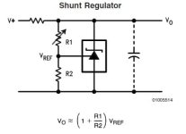
The formula is:

VZ= 2.5 (1 + R1/R2) + .002 x R1

With some flavors, the 2.5 term may be closer to 2.49. The .002 term compensates for the current consumption of the 431. This may vary a bit also.

From the datasheet:

431 voltage divider.jpg
 
Finally got around to hooking the boards up to a power supply (actually 3 in series). Set the voltage around 105 volts, hooked it up across the boards (no cells attached) and each circuit equalized to around 3.5 volts. No shunt LED's were lit up. Cranked it up, as soon as I hit 108 volts (3.6v per cell) all the shunts lit up at once. Couldn't find any irregularities. Really stumped on this one...
 
Hmmm...
It seems like the circuits test OK like that. Yes, they should all light up at the same time. That's a good sign.

You might try measuring between adjacent pins on the connector going to the pack to see if you're getting the right cell voltages. You have to be very careful to avoid shorting the probes. It really seems like one of the tap wires is either swapped or open somewhere. Do this without plugging in the board.
 
Look for something like a pinched or broken wire. Testing the voltages at the connector is a good test.
 
Voltage is good across every connection coming from the pack, every cell at 3.35 volts except for the ones connected to the trouble LED's are a bit lower, cell one is at 2.82 volts (others problem ones are at 3.29 volts). Have some spare time this weekend so I'd like to get this BMS working so I can finally ride my bike!
 
Hmm...

I'm kind of running out of suggestions on what to check. Seems like the board works fine when it's not connected to the pack. About the only other test I might suggest is to use the power supply and energize the board a few cells either direction of the suspect channels without going through the control circuit (just use jumper clips on the big resistors) and get the current up to the point where the opto triggers and see how much that is. All channels should trigger around 0.5A. You can just use a meter in ohms or diode check mode on the HVC line that connects all the opto outputs to tell when it triggers.

Don't run it too long at full current, the resistors will get hot fast.
 
I guess I was thinking it would be good to test the cell circuits to see at what current the opto gets activated and kills the charge current. When the problem happens, it seems like this is way too low.
 
So , my name is Albert and i live in Barcelona.I'm a proud owner of a vectrix maxiscooter , and 6000 18650 recicled laptop cells I'm testing.So my question is if i can modify the resistors on the bms board to work with a pack of 7 kwh to 20 kwh?

The nominal tension of thepack would be 137 volts nominal 157 peak and 111 volts minimum.Theoretically there's no problem with that , because i could daisy chain it.


The Real problem would be the DaRt systems the vectrix uses instead of an analogic hall sensor throttle.So i would need to codify the digital signal of the throttle or bypasse it or change the low voltage protecction to another method compatible with the bms.

So , i would apreciate any suggestions and forgive my poor english cause it,s not my mother tongue.
 
The BMS will work with Li-ion laptop cells. Your numbers indicate around 38 series cells. This board has been used with 40s cell packs sucessfully.

Interfacing to the throttle may be difficult, but you could possibly interface to the brake switch instead.
I don't have a Vectrix, but I assume if you apply the brakes, the throttle will automatically go to zero. There should be a way to tie into that.
One test would be to try measuring the the voltages on the wires going to the brake switches. Battery negative is usually the reference. Measure with power on try with and without pulling the brake.

Another option is to not interface the LVC to the scooter but use an alarm beeper instead. Human has to let off the throttle when it beeps. This is fairly simple to set up.
 
HALL9000 said:
The Real problem would be the DaRt systems the vectrix uses instead of an analogic hall sensor throttle.So i would need to codify the digital signal of the throttle or bypasse it or change the low voltage protecction to another method compatible with the bms.
If it's a continuous serial digital signal from the throttle, *and* the vectrix brain is smart enough to kill the motor when it no longer receives it, it should be very simple to use a logic gate to combine teh LVC signal with the throttle. (AND or NAND, etc). Then only when the LVC is not active, would the throttle signal get thru. Otherwise the brain would shut down the controller.

IF the signal isn't continous, or the brain doesn't shutdown when it isn't receiving it, or the brain won't restart once it gets it again, then that won't work.

Easy experiment to do, though.
 
Fetcher: I'don't know if the vectrix killswicthes when braking , but i doubt it.I think the only digital signal tha the brakes implies , the launch sequence , a kind of security password by pressing the levers to ignitethe vectrix.If if daisy chain to obtain feedback for the 37s//38s , have i must chage resistors or something in your desing , or Can i follow the normal instructions or buying list in the zhephyr web//instrucctions manual?


Maybe the continuos killswitch aproach with the LCV maywork , wich kind of hardware do you think i would need amberwolf?


Thank you for all the replies.
 
The Zephyr LVC circuit is just a bunch of opto couplers that will activate when a cell goes too low.
This is about the same as a switch that turns on. You need to find a spot on the scooter where you can kill the motor by switching a line to ground or 5v or similar. You could test by just placing a jumper across the suspect spot and see if it stops the motor.

If necessary, you could add a relay, but that should be avoided if possible.

Unfortunately, I don't know much about the Vectrix and where you would do this.

Most scooters, if you have the throttle on and at the same time pull the brake lever, the power to the motor stops immediately. You could try this. If that works, then finding the brake switch wires and measuring the voltages on them should be easy.
 
Hi Fechter.
Do you think the zephyr would be ok to keep up with fast charging, at around 65A?
 
The charge control FET is good for around 20A. Higher rates would be possible if there is a way to interface to the charger.
Higher rates could also be possible by using more charge control FETs in parallel, but it would be better to skip those and throttle the charger directly.
Zivan chargers I was looking at some time ago have a thermistor input that can be interfaced to the Zephyr board to cut the charge current when cells reach HVC.
 
fechter said:
The charge control FET is good for around 20A. Higher rates would be possible if there is a way to interface to the charger.
Higher rates could also be possible by using more charge control FETs in parallel, but it would be better to skip those and throttle the charger directly.
Zivan chargers I was looking at some time ago have a thermistor input that can be interfaced to the Zephyr board to cut the charge current when cells reach HVC.

Thanks i think the 3000W charger i want to use for charging only has CANBUS enable/disable pins, so maybe overriding the charge control until the level of charge reduces to within the Zephyr specs, do you think that might work, wait the 20 mins or so till charge level reduces then connect in the charge control ?
Will the Zephyr still carry out balancing without charge control and can it handle levels of balancing currents that might be expected with the 65A charge current?
 
You can choose FETs with the ratings you need. The board will drive most common types.
Normally IRFB4110 would be specified, but those are rated for 100V. There may be some new choices out there these days.

The FET only really needs to handle the difference between the pack voltage and the charger. When the pack is low the voltage difference will be the greatest. I recommend using FETs that handle the full charger voltage to have some safety in case the pack is disconnected somewhere. Installing the TVS diode across the FET will help prevent overvoltage damage to the FETs.

Bigger FETs may not fit on the board, but could be mounted off board and attached by wires.

What kind of charger are you using?
 
My vectrix mounts a runke "gold" charger in it's peak will charge about 1800 w. Now I a have i firmware that's only charging at 1100 watts.The pack will be from 10 KWH to about 17 KWH.

Thank you...
 
I couldn't find much on the Runke charger. I suspect it does have some kind of interface for the BMS.

There's no guarantee the charger will play nice with the Zephyr board when it goes into throttling. Some chargers will see the drop in current as a sign the charge is complete and stop short of a full charge.

What is the peak voltage/current?
 
Now that i have a new firmware , is about 152 volts and 6 amps aprox.But if i get a bigger battery pack i planned to return to the old charging programe that is about 152/153 volts 11,5 A.
 
By the way , this charger is the one that's in the lithium version of the vectrix.The lithium version has it's oen propietary bms looking for a lifepo4 battery pack , so i suspect that this would not a be a problem , cause in adittion to the fact that the runke is compatible with a bms , a lot of people had converted their vectrix to better lithium upgrades.
 
Back
Top