
You are using an out of date browser. It may not display this or other websites correctly.
You should upgrade or use an alternative browser.
You should upgrade or use an alternative browser.
"Zephyr" - Finally, the "v4" Fechter/Goodrum/Hecker BMS...
- Thread starter GGoodrum
- Start date
When I complete this BMS I was planing on using it with a Vpower charger, this charger holds 30.4 volts on the CV phase, so i'll have to find a way of lowering the voltage to 28.8 to 29.2, but the main thing about this charger is it puts out 5amp until it reaches the CV voltage then goes to 100ma or so, it doesn't ramp down the current as the voltage rises, will this be o.k, will 5 amps near the end of charge be o.k for this BMS to dissipate or will i have to invest in a more expensive / smart charger?.
as far as i can work out the hvc will start to pulse so reducing the heat that the shunts will have to deal with.
Jim
as far as i can work out the hvc will start to pulse so reducing the heat that the shunts will have to deal with.
Jim
Actually it sounds like you need a 'dumber' charger. You'll have to see what happens. If the cells are all closely matched, the BMS doesn't have to do much. If imbalance causes the HVC to trip, I don't know how that charger is going to behave. Hopefully it restarts at full current.
Sorry, not at this time. Gary and I are working on a surface mount version that can be machine made. Since both of us are flat broke, this will take quite a while to get going.
MrEco said:Is there any other option to buy assembled Goodrum/Fechter BMSs? Our need is 23pcs right now.
Cheers
Rickard
Sorry, not at this time. Gary and I are working on a surface mount version that can be machine made. Since both of us are flat broke, this will take quite a while to get going.
Zenid
100 W
Any chance of feedback on this?Zenid said:D1 diode checks out - same readings as its counterpart across on the other side. All the other diodes look fine too.
I also re-ran the light-bulb voltage tests. The first bank looks to have the same voltage as the rest, but - like last time - the voltages aren't steady and seem to wobble up and down quite a bit.
Recap: The board worked a couple of times, then went flaky and died.
80V goes into Q1, no 12V coming out, diode is OK.
Gregb
100 W
what is the voltage across each side of R1? voltage at junction of c2,r3, d2? at r5,r4? (this should be just above grd. Is the eoc link removed? V acros each pin?? v across neg side of D3 ? what happens if you vary VR1? does the voltage across the wiper vary?
Gregb
100 W
Hobby king have just confirmed to my question they no longer intend selling the cell-log. No reason given
10 kW
Sorry to join the party late. Just started getting into assembling my own packs from LiPO. Are these boards still available? I went back to the beginning of the thread but the original links to the website "tppacks.com" or whatever it is seems to be broken. Would like to try one of these. Was originally intiminated by the amount of soldering but have been brushing up on latest project with an 18s LiPO powered hub motor bike.
GGoodrum
1 MW
Zenid said:Any chance of feedback on this?Zenid said:D1 diode checks out - same readings as its counterpart across on the other side. All the other diodes look fine too.
I also re-ran the light-bulb voltage tests. The first bank looks to have the same voltage as the rest, but - like last time - the voltages aren't steady and seem to wobble up and down quite a bit.
Recap: The board worked a couple of times, then went flaky and died.
80V goes into Q1, no 12V coming out, diode is OK.
If you aren't getting 12V out of the source of Q1, my guess is either D1 or D2 is fried. I'm guessing D1 is dead shorted. It has been my experience when a zener fails, it fails as a dead short. If D2 failed, I'd expect it to actually come apart, as there's no limit on the current. Anyway, you can use the diode mode of your meter to check both directions across both zeners. In one direction, it should read nothing, and in the other, something like .6V. If either is bad, it will read as a dead short (0.00V).
-- Gary
GGoodrum
1 MW
pdf said:Sorry to join the party late. Just started getting into assembling my own packs from LiPO. Are these boards still available? I went back to the beginning of the thread but the original links to the website "tppacks.com" or whatever it is seems to be broken. Would like to try one of these. Was originally intiminated by the amount of soldering but have been brushing up on latest project with an 18s LiPO powered hub motor bike.
Yes, they are. Just send me a PM, or an email (ggoodrum@tppacks.com). The web hosting service I had used for years apparently went under, as they literally just pulled the plug on both my website and email server, with no notice. They never responded to a single email about this either. Unfortunately, I didn't have a current backup of the site, so I lost everything, and now have to start from scratch. I have a new host, and I have the email up and running, but it is going to take me a week, or so, before I can get a new website up and running.
In the meantime, just send me a PM/email, if you want one. The 16-channel board is $79 and the 24-channel is $99. Shipping is about $5 for within the US, and about $15 for outside.
-- Gary
fechter said:Actually it sounds like you need a 'dumber' charger. You'll have to see what happens. If the cells are all closely matched, the BMS doesn't have to do much. If imbalance causes the HVC to trip, I don't know how that charger is going to behave. Hopefully it restarts at full current.
MrEco said:It would be helpful if a list could be compiled of the suitable chargers. It could start with educated guesses and be refined as experience is gained. I would suggest either doing it on this thread and making a condensed version on another short thread (maybe a stickie) or simply starting another thread. I am new to using these batteries and I have no clue what charger to buy for use with this board.
Zenid said:Okay. 80V makes it through the fuse and that diode on the other side (D3) to the middle pin ("D") of Q1. But I see no voltage at all on the top (G) pin or the bottom (S) one.fechter said:You want to poke around Q1 to check the voltage regulator first.
You should be getting full charger voltage on both sides of the fuse.
You should have 15v on the gate pin, and about 12v on the source pin.
Thanks for your continuing help! Perhaps this workthrough could be the basis of a troubleshooting section in the manual.
About the only way that can happen is if the zener D1 is shorted or R1 is open. You need to see 15v on the gate of Q1 before you can get any output.
Without that, nothing else will work. Check D1 with a diode check meter (no power). If it reads zero, replace it. D1 is the most likely part that failed.
MrEco said:It would be helpful if a list could be compiled of the suitable chargers. It could start with educated guesses and be refined as experience is gained. I would suggest either doing it on this thread and making a condensed version on another short thread (maybe a stickie) or simply starting another thread. I am new to using these batteries and I have no clue what charger to buy for use with this board.
Unfortuantely there are dozens of different chargers out there and manufacturers tend to change the design often.
Andy tested with a Thundersky and Elcon charger. Several people have used plain CC-CV power supplies like the Meanwell or Mastech.
Zenid
100 W
D1 and R1 are fine. But then I found a burnt out track by the fuse:fechter said:About the only way that can happen is if the zener D1 is shorted or R1 is open. You need to see 15v on the gate of Q1 before you can get any output.
Without that, nothing else will work. Check D1 with a diode check meter (no power). If it reads zero, replace it. D1 is the most likely part that failed.
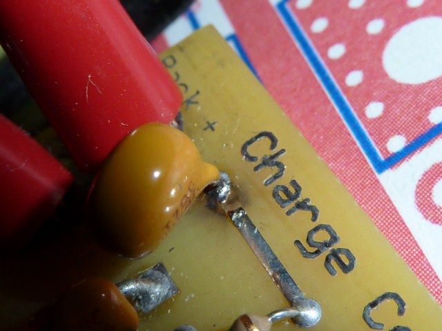
This has now been repaired. But now when I do the light-bulb test, running 80V from my 'dumb' charger to the board (through the charger input wires) via my light-bulb, the bulb lights up brightly indicating something is seriously wrong, - probably whatever resulted in the track burning out. There is no continuity across the charger input wires, though.
Here's a picture of the area, showing components and markings on Q1, Q3 etc.
http://zenid10.files.wordpress.com/2011/06/p1030254-640x480.jpg
You must have accidently touched a wire to the wrong spot at one point to blow the trace off.
With the light bulb in place, try measuring the voltages on the pins of Q1. If Q1 is good, something down stream is likely to be shorted.
With the light bulb in place, try measuring the voltages on the pins of Q1. If Q1 is good, something down stream is likely to be shorted.
Zenid
100 W
I remember getting a spark up there when I attached the jumper to do the voltage calibration for my charger. But everything continued to work fine afterwards so I thought nothing of it.fechter said:You must have accidently touched a wire to the wrong spot at one point to blow the trace off.
Thanks for your help by email. Just to update folk, we thought it might be D2, so I replaced that, but I get the same readings off the board as I did before, and nothing has changed with the light-bulb test. Strangely, the one I replaced reads as faulty.fechter said:With the light bulb in place, try measuring the voltages on the pins of Q1. If Q1 is good, something down stream is likely to be shorted.
So now we reckon it's one of U1, U2 or U3. It would be nice if there would be some way of figuring out which of these is actually faulty, as replacing these components is a horrible ordeal.
Also, though Mouser are relatively inexpensive from within the US, their UK (or European) branch are an obscene rip-off and I am loathe to want to do any more business with them. They charge £12 ($20) just to deliver anything, even if it's a component the size and value of a peanut. And everything looks at least twice as expensive as it should be.
Since I seem to have little choice, it would make sense for me to assemble a small list of control circuit components covering anything that might conceivably have broken down or gotten damaged here, and which it would be best to get from Mouser to be sure I have the right parts. I'm thinking just the U1/U2/U3 chips, but if there's anything else that might be difficult to source locally, perhaps I should include those too. Suggestions?
In the mean time I would appreciate it if you could rack your brains for a test that can more specifically identify or eliminate suspect components.
Gregb
100 W
On the question of suitable chargers: while there are too many brands available to recommend would it be possible to list basic requirements? eg is basic transformer bridge rectifier (SLA) type suitable ? Is a switch mode better?
should it be CC/CV capable ?; point at which changeover should best occur; charge current capability ; Max voltage. whether max/min should be adjustable. and any other points you feel are relevant or worthwhile,,,...
This could possibly be included in the new page for the board.
Greg
should it be CC/CV capable ?; point at which changeover should best occur; charge current capability ; Max voltage. whether max/min should be adjustable. and any other points you feel are relevant or worthwhile,,,...
This could possibly be included in the new page for the board.
Greg
Most any charger that has current limiting and an adjustable output voltage should work. You can run into problems if the charger is 'smart' and wants to shut down when the charge current drops during HVC throttling. CC-CV 'dumb' power supplies like the Meanwell are ideal. Most lead-acid chargers will also work.
The behavior of a particular charger may be hard to tell without acutal testing as the software varies widely.
The behavior of a particular charger may be hard to tell without acutal testing as the software varies widely.
Gregb
100 W
Has anybody managed to get this working? I am going to cut my losses of $200.00 and bin it. It is far too susceptible to static damage and the design of the board makes it impossible to remove components without breaking them. I think it will work as designed but I don't think it is suitable for amateur construction and I am no amateur. Seeing that I have paid for it I may try and redesign the board for my personal use. This will not be for sale or even giving away. They have put the hard yards in and it is their creation. For now I will just continue with my bulk charger and occasionally rebalance one cell at a time.
Best of luck to you all..
Best of luck to you all..
Lessss
1 MW
Zephyr bms looking for website to buy. ttpacks sems to be dead. Is there a replacement site?
Gregb
100 W
Gary is working on it. see earlier post this thread. he only sells board and instructions. You build.
Gregb said:Has anybody managed to get this working? ..
Yes, Andyh and Gary have working versions of it. It is definitely not a good beginner project and requires a fair amount of soldering skill.
We are moving ahead with trying to get a pre-built surface mount version of it going. I hate building those things as much as anybody. It's a lot of little parts.
deVries
100 kW
I know Geoff was interested at one time in helping to do the SM version of these, but you were upgrading the design too often last year.fechter said:Gregb said:Has anybody managed to get this working? ..
Yes, Andy and Gary have working versions of it. It is definitely not a good beginner project and requires a fair amount of soldering skill.
We are moving ahead with trying to get a pre-built surface mount version of it going. I hate building those things as much as anybody. It's a lot of little parts.
If you do a SM version I hope it will still be possible to do that mod you mentioned to allow for different LVC settings to be used?
I'll finally be in the market for these this year or next, so I'm lucky you've got a design you're finally happy with. It really has been a work of determined effort over years of development, so you guys really deserve our admiration & appreciation for your contribution to ES.
Thanks! 8)
Zenid
100 W
Following Richard's instructions I've managed to figure out and repair the problem. 
To eliminate Q1 as a suspect, I lifted the bottom (source) leg on Q1 and measured voltages with it detached from the board, I got the expected 12V or so, so I put the leg back again. I also had the expected readings of 14V and 80V on the top (g) and middle (d) pins respectively.
This meant that it had to be something further 'downstream', and that I should look at U1, U2, and U3 next. Richard suggested snipping the source pins to each of these chips in turn to see what made the short go away, once there was no longer continuity between the ground and the 12V rail, then that should be my culprit.
First I went to U1 and cut pin 8. It made no difference: I was still measuring 0Ω across the charger input ground and the 12V rail. So next I cut pin 6 on U3 (the source for U3 and U2) and this did it! I no longer showed a short across GND and the 12V rail.
By luck, I had a spare U3 chip left over from my Mouser order, as the board had already come fitted with U2 (this was part of fixing a 'bug' in this version of the board), leaving me with one left over (U2 and U3 use the same chip). So I carefully removed the one on the board and replaced it with a socket. Richard suggested using sockets for these chips to make replacement easier, as replacing the chips is quite tedious and time consuming.
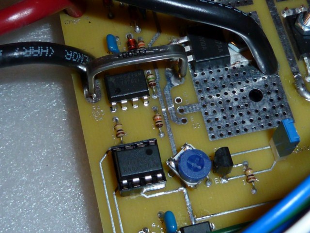
U3 now sits in a socket
Obviously there was still the matter of the snipped pin on U1: For this, I just bent the snipped ends back together again and used a blob of solder to effect a repair. This done, I fired it all back up again - through the light-bulb at first - and I had my little green LED back again It's all now up and running again, charging as it did before.
Thanks a lot to Richard and Gary for being so patient in helping me troubleshoot and fix this! It's been frustrating for everyone, but at least we have a basic troubleshooting path for figuring things like this out. I think the biggest lesson to come out of this is to use sockets for U1, U2, and U3, as this would have made figuring this out and fixing it so much easier. Perhaps three sockets should be added to the parts list, and the next version of the instructions amended to recommend that these chips be unpluggable in this way, as that could greatly simplify troubleshooting!
As for how U3 go damaged in this way - I think Richard mentioned that U3 might be prone to damage from static from the EOC jumper, and when I was trying to get the EOC cut-off to function I did a lot of fiddling with that jumper, often just shorting it with a screwdriver end as I tried to figure out what was going on, perhaps that's what killed it off...
Incidentally, I am still back at this original issue, which is that the whole thing only seems to work with the EOC jumper on. Any thoughts on what could be going on here would be appreciated, as it needs to be able to turn itself off once it's done...
To eliminate Q1 as a suspect, I lifted the bottom (source) leg on Q1 and measured voltages with it detached from the board, I got the expected 12V or so, so I put the leg back again. I also had the expected readings of 14V and 80V on the top (g) and middle (d) pins respectively.
This meant that it had to be something further 'downstream', and that I should look at U1, U2, and U3 next. Richard suggested snipping the source pins to each of these chips in turn to see what made the short go away, once there was no longer continuity between the ground and the 12V rail, then that should be my culprit.
First I went to U1 and cut pin 8. It made no difference: I was still measuring 0Ω across the charger input ground and the 12V rail. So next I cut pin 6 on U3 (the source for U3 and U2) and this did it! I no longer showed a short across GND and the 12V rail.
By luck, I had a spare U3 chip left over from my Mouser order, as the board had already come fitted with U2 (this was part of fixing a 'bug' in this version of the board), leaving me with one left over (U2 and U3 use the same chip). So I carefully removed the one on the board and replaced it with a socket. Richard suggested using sockets for these chips to make replacement easier, as replacing the chips is quite tedious and time consuming.
U3 now sits in a socket
Obviously there was still the matter of the snipped pin on U1: For this, I just bent the snipped ends back together again and used a blob of solder to effect a repair. This done, I fired it all back up again - through the light-bulb at first - and I had my little green LED back again
It's all now up and running again, charging as it did before.
Thanks a lot to Richard and Gary for being so patient in helping me troubleshoot and fix this! It's been frustrating for everyone, but at least we have a basic troubleshooting path for figuring things like this out. I think the biggest lesson to come out of this is to use sockets for U1, U2, and U3, as this would have made figuring this out and fixing it so much easier. Perhaps three sockets should be added to the parts list, and the next version of the instructions amended to recommend that these chips be unpluggable in this way, as that could greatly simplify troubleshooting!
As for how U3 go damaged in this way - I think Richard mentioned that U3 might be prone to damage from static from the EOC jumper, and when I was trying to get the EOC cut-off to function I did a lot of fiddling with that jumper, often just shorting it with a screwdriver end as I tried to figure out what was going on, perhaps that's what killed it off...
Incidentally, I am still back at this original issue, which is that the whole thing only seems to work with the EOC jumper on. Any thoughts on what could be going on here would be appreciated, as it needs to be able to turn itself off once it's done...
OK, good work there. It was challenging to come up with testing and troubleshooting procedures that did not involve any speciallized test equipment. Light bulb and a voltmeter can get you pretty far.
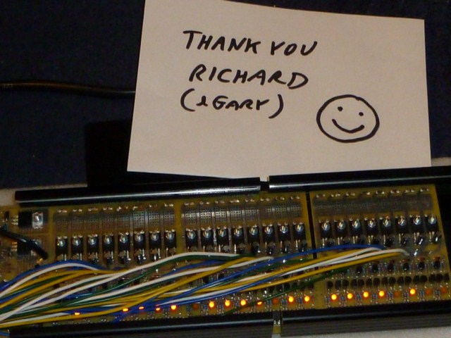
NOW you officially earn the coveted guinea pig award!

NOW you officially earn the coveted guinea pig award!
Zenid
100 W
LOL. Thank you! I shall treasure it...fechter said:OK, good work there. It was challenging to come up with testing and troubleshooting procedures that did not involve any speciallized test equipment. Light bulb and a voltmeter can get you pretty far.
NOW you officially earn the coveted guinea pig award!
How that guy looks is pretty much how I've felt this last couple of weeks. :lol:
It's really important to have these low-tech troubleshooting paths, otherwise less experienced hobbyists without lots of posh equipment are going to be put off for fear of being sent up the creek without a paddle if things go wrong.
I'll let you know how the EOC goes once I've fixed that pot.
Similar threads
- Replies
- 7
- Views
- 4,775