methods
1 GW
Wow... I lost a couple of weeks. Time just flies...
So Some time back, around when the CroMotors landed I managed to squeeze in an entire day at Starbucks playing with different layouts. Again, the goals were:
* All surface mount parts that can be placed with tweezers and baked on with solder paste
* No hand work including beefing up traces, cutting legs, etc
* Low parts count, smallest board possible
Now if you are reading this thinking that you want to have a go with OSH park - let me share a few important tips.... ok, one tip - the most important...
PRINT OUT YOUR CIRCUIT AND SET THE PARTS ON IT
That is the most important thing you can do if you are inexperienced and you want to win. So much can be learned - and things that were not obvious before become obvious. Here is a version of my board and what I learned by looking at it with parts on it.
First - lets recall some lessons learned so we know why I did it the way I did this time (i.e. what was fail last time)
* Soldering in thru-hole fets that need a heat sink is FAIL - added complexity, expense, etc. Laying the fets down to heat sink through the board into the cabling is FTW!
* Beefing up traces is FAIL - a PCB should be designed such that it does not require traces to be beefed up at time of manufacture. It is time consuming, complicated, the boards warp, it just sucks. The way to win... is to have the user do the work by replacing the traditional thru-hole with a big long landing strip. In this way the end user lap-solders their wire to the board which beefs up the traces, creates a heat sink, and makes for a very strong bond.
Ok - what are we looking at here:
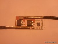
Swapped the TO-220 package for a surface mount package. One less leg to solder, no thru-hole issues under the board, smaller footprint, nominal cost increase.
The green bars represent 10AWG cable. First look at the bottom left - see how the wire runs parallel to the two fet bodies? Those are the drains and they connect directly to the wire (good electrical path) and there is a reasonable heat path. Vias are not shown - but they are there.
The sources are the legs in the upper right. See how they have a reasonable path to the cabling? It is assumed that the user will float the solder a bit and beef those traces up at the time of solder. We will of course offer a version where we do this for folks - but we are really trying to get away from that as it is very time intensive.
The upper left hand corner has a JST-XH-2 connector on there (actually it is on the bottom I think...). Could be used as the HVC input or the user ON/OFF control. Just a place holder - Kywin will make up a set of custom cables for us so we have not decided on a connector yet
In the lower right hand corner we have the Attiny. I tried to keep it as far away from the heat as possible. Ah - see a lesson learned? See how tightly I packed those capacitors? That is a fail - too easy to bump one cap while laying another. Some spacing will need to happen to make it a produce-able design
There is another JST-XH-2 above the uController. That too I believe is on the bottom. COuld be HVC or Power. Just a place holder
The regulator can be seen - it probably could use a better thermal pad. Speaking of which - the polygons have not been drawn yet but all of these thermal traces have matching pairs on the back side.
The 6 pin header is another place holder for the in-circuit programming port. I will probably just make them pads and build up a little pogo for it. Placeholder
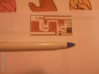
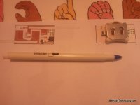
Ok - I have just fallen out of love with these coin cells. To do two of them stacked the holder is HUGE. HUGE HUGE HUGE. In my mind I was picturing the tiny little 40mAh cells on my RTC GizMo board - in reality I choose the much larger CR2032 - and a huge holder for them. Looking at this makes me think fail - not sexy at all.
Seems to me what would be much more sexy is one of those tiny little micro-helicopter batteries plugged in. You know - the ultra tiny little pouch cells that sometimes have a little plastic housing around them. Most are 1S I think - but I am sure that some are 2S. Opens up a whole new can of worms... I guess I could just hard-solder in a little lipo pack and leave a charging port. Supply one of those crappy little USB chargers - bah. Bummed that my whole coin cell thing kind of flopped.
Anyway - you can also see that the footprint I made for this battery holder was not very good. Truth told - I made a foot print to the manufacturers spec and did not like it. This is just a standard Spark Fun footprint that I figured I would tweak later. I am pretty sure that in the end folks always end up wanting bigger pads for these things...
Changing subjects: I did not meet a few of my requirements:
* Battery holder is on the bottom of the board, so will need hand soldering
* There are two thru-hole JST-XH connectors... they will require hand soldering (or dipping - but I dont think they can take an oven bake)
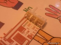
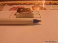
View attachment 2
See how tall that fugger is? Ugh... what a fail.
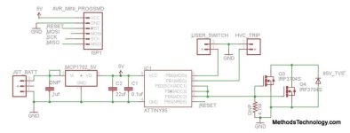
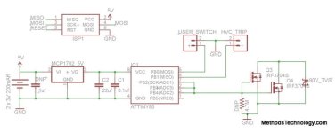
Below is the current schematic. A few realizations happened.
* A 5V regulator is required
* A pull down resistor is probably required (though I will test without it)
* The circuit will stay on 24/7 - brown out will be turned off any time the fets are off.
* We are pretty short on pins - sigh...
* Gates are now tied together and not on a PWM pin. 3 drivers, 2 gates, no gate resistor (I think they will be fine) I can play with rise time by the number of driver pins attached
Some bads:
* We are tied to the logic level fet - so that means 100V across it until someone comes out with a >100V high quality gate drive power fet. For charging this is not a limitation - but for discharging or turning the controller on and off 100V will be the limit. Hmmm... I guess we could get clever and use these fets to switch some other fets (ugh...)
* Still no hardware test has been done
* We are depending on the end user to make the heat sink... if they are using a 10W crappy RadioCrack soldering iron and 10AWG high strand count Hobby City wire there is a good chance of poor solder joints. We may have to re-think this part. I think that anyone who is serious about DIY electronics basically MUST own a 200W soldering iron. They are like $30 at almost any store (the weller gun style with two power levels). Quality is low but if use is low they will last a lifetime.
Here is the current state of the schematic.
Today I plan to think some more about the layout. I want to eliminate the thru-hole connectors, possibly replace the coin cells, talk to Keywin about what kind of harness he can build for us, think about options for pigtailing that dont take a bunch of labor, confirm that this uController will do what I need it to, set up a proof of concept circuit, order some logic level surface mount fets, and... oh yea... GO TO THE BEACH
I got a new surf board
It is a wretched old 9' 2" board that looks like it crawled out of someones ass and died. There are more patches and cracks on it than original material... it has a fin the size of my leg... but I took it out to Pleasure Point yesterday (there were like 75 people in the water) and I rode one wave for an interval of time longer than all of my previous rides combined. I started surfing as a kid in Junior High - we lived like 300 steps from the beach... but I wanted to be cool so I got a short thrasher board... then I basically just posed on the beach and out in the water because I could not even stand up on it. Anyway - now I have a proper learning board and I am going to add one more skill to my bag of tricks. Surfing.
Here is what Pleasure Point looks like - an international surfing destination.

Tell me that you dont want to ride those?
At low tide you can walk out like 200 yards... basically you can ride a wave for 30 seconds+ in knee deep water. The location is beautiful too...

So - hopefully by the time you are reading this over-written crap I will be there riding waves in the sun. Sometimes I forget that THIS is why I quit my job... not to toil over bullshit... but to live the dream.
-methods
So Some time back, around when the CroMotors landed I managed to squeeze in an entire day at Starbucks playing with different layouts. Again, the goals were:
* All surface mount parts that can be placed with tweezers and baked on with solder paste
* No hand work including beefing up traces, cutting legs, etc
* Low parts count, smallest board possible
Now if you are reading this thinking that you want to have a go with OSH park - let me share a few important tips.... ok, one tip - the most important...
PRINT OUT YOUR CIRCUIT AND SET THE PARTS ON IT
That is the most important thing you can do if you are inexperienced and you want to win. So much can be learned - and things that were not obvious before become obvious. Here is a version of my board and what I learned by looking at it with parts on it.
First - lets recall some lessons learned so we know why I did it the way I did this time (i.e. what was fail last time)
* Soldering in thru-hole fets that need a heat sink is FAIL - added complexity, expense, etc. Laying the fets down to heat sink through the board into the cabling is FTW!
* Beefing up traces is FAIL - a PCB should be designed such that it does not require traces to be beefed up at time of manufacture. It is time consuming, complicated, the boards warp, it just sucks. The way to win... is to have the user do the work by replacing the traditional thru-hole with a big long landing strip. In this way the end user lap-solders their wire to the board which beefs up the traces, creates a heat sink, and makes for a very strong bond.

Ok - what are we looking at here:
Swapped the TO-220 package for a surface mount package. One less leg to solder, no thru-hole issues under the board, smaller footprint, nominal cost increase.
The green bars represent 10AWG cable. First look at the bottom left - see how the wire runs parallel to the two fet bodies? Those are the drains and they connect directly to the wire (good electrical path) and there is a reasonable heat path. Vias are not shown - but they are there.
The sources are the legs in the upper right. See how they have a reasonable path to the cabling? It is assumed that the user will float the solder a bit and beef those traces up at the time of solder. We will of course offer a version where we do this for folks - but we are really trying to get away from that as it is very time intensive.
The upper left hand corner has a JST-XH-2 connector on there (actually it is on the bottom I think...). Could be used as the HVC input or the user ON/OFF control. Just a place holder - Kywin will make up a set of custom cables for us so we have not decided on a connector yet
In the lower right hand corner we have the Attiny. I tried to keep it as far away from the heat as possible. Ah - see a lesson learned? See how tightly I packed those capacitors? That is a fail - too easy to bump one cap while laying another. Some spacing will need to happen to make it a produce-able design
There is another JST-XH-2 above the uController. That too I believe is on the bottom. COuld be HVC or Power. Just a place holder
The regulator can be seen - it probably could use a better thermal pad. Speaking of which - the polygons have not been drawn yet but all of these thermal traces have matching pairs on the back side.
The 6 pin header is another place holder for the in-circuit programming port. I will probably just make them pads and build up a little pogo for it. Placeholder

Ok - I have just fallen out of love with these coin cells. To do two of them stacked the holder is HUGE. HUGE HUGE HUGE. In my mind I was picturing the tiny little 40mAh cells on my RTC GizMo board - in reality I choose the much larger CR2032 - and a huge holder for them. Looking at this makes me think fail - not sexy at all.
Seems to me what would be much more sexy is one of those tiny little micro-helicopter batteries plugged in. You know - the ultra tiny little pouch cells that sometimes have a little plastic housing around them. Most are 1S I think - but I am sure that some are 2S. Opens up a whole new can of worms... I guess I could just hard-solder in a little lipo pack and leave a charging port. Supply one of those crappy little USB chargers - bah. Bummed that my whole coin cell thing kind of flopped.
Anyway - you can also see that the footprint I made for this battery holder was not very good. Truth told - I made a foot print to the manufacturers spec and did not like it. This is just a standard Spark Fun footprint that I figured I would tweak later. I am pretty sure that in the end folks always end up wanting bigger pads for these things...
Changing subjects: I did not meet a few of my requirements:
* Battery holder is on the bottom of the board, so will need hand soldering
* There are two thru-hole JST-XH connectors... they will require hand soldering (or dipping - but I dont think they can take an oven bake)
View attachment 2
See how tall that fugger is? Ugh... what a fail.
Below is the current schematic. A few realizations happened.
* A 5V regulator is required
* A pull down resistor is probably required (though I will test without it)
* The circuit will stay on 24/7 - brown out will be turned off any time the fets are off.
* We are pretty short on pins - sigh...
* Gates are now tied together and not on a PWM pin. 3 drivers, 2 gates, no gate resistor (I think they will be fine) I can play with rise time by the number of driver pins attached
Some bads:
* We are tied to the logic level fet - so that means 100V across it until someone comes out with a >100V high quality gate drive power fet. For charging this is not a limitation - but for discharging or turning the controller on and off 100V will be the limit. Hmmm... I guess we could get clever and use these fets to switch some other fets (ugh...)
* Still no hardware test has been done
* We are depending on the end user to make the heat sink... if they are using a 10W crappy RadioCrack soldering iron and 10AWG high strand count Hobby City wire there is a good chance of poor solder joints. We may have to re-think this part. I think that anyone who is serious about DIY electronics basically MUST own a 200W soldering iron. They are like $30 at almost any store (the weller gun style with two power levels). Quality is low but if use is low they will last a lifetime.

Here is the current state of the schematic.

Today I plan to think some more about the layout. I want to eliminate the thru-hole connectors, possibly replace the coin cells, talk to Keywin about what kind of harness he can build for us, think about options for pigtailing that dont take a bunch of labor, confirm that this uController will do what I need it to, set up a proof of concept circuit, order some logic level surface mount fets, and... oh yea... GO TO THE BEACH
I got a new surf board
It is a wretched old 9' 2" board that looks like it crawled out of someones ass and died. There are more patches and cracks on it than original material... it has a fin the size of my leg... but I took it out to Pleasure Point yesterday (there were like 75 people in the water) and I rode one wave for an interval of time longer than all of my previous rides combined. I started surfing as a kid in Junior High - we lived like 300 steps from the beach... but I wanted to be cool so I got a short thrasher board... then I basically just posed on the beach and out in the water because I could not even stand up on it. Anyway - now I have a proper learning board and I am going to add one more skill to my bag of tricks. Surfing.
Here is what Pleasure Point looks like - an international surfing destination.

Tell me that you dont want to ride those?
At low tide you can walk out like 200 yards... basically you can ride a wave for 30 seconds+ in knee deep water. The location is beautiful too...

So - hopefully by the time you are reading this over-written crap I will be there riding waves in the sun. Sometimes I forget that THIS is why I quit my job... not to toil over bullshit... but to live the dream.
-methods


