Awesome - you have repeated your simple solution that does not meet the design requirements.
How is that going to stop charge current in an HVC event?
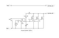
Where is the power going to come from that runs through that switch and energizes the opto?
What kind of BMS has an active high output?
Where does that address PreCharge?
With the number of discrete components you would need to get that working (including the ultra wive voltage regulator you would need that is not shown) it would be more parts and be less useful - i.e. that circuit will only work for that application in that voltage range.
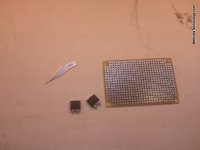
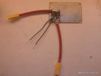
For the same number of parts I can create a switch that is good for 0V to 150V, 0A to 50A, requires no connection to VCC, can be hooked up high side or low side, can break charge current, or break controller regulator power, or just work inline with a 4S accessory pack, or - it can work with any DIY guys one-off application. It draws no current form the main stack whether ON or OFF. It has minimal wiring and fuss. It can protect against HVC and LVC with our without an external switch.
Nothing drives me more crazy then folks who ignore the design intent and just post deceptively simple "solutions" that distract from the goal. If that is the solution then please build it, test it, document it, produce it, and make it available for people to purchase it. Lets see if you can sell enough of them to even cover your cost in parts, labor, and customer support. You will find out quickly that your limited solution will not meet the wide range of requirements that the members have.
-methods
circuit said:
draws almost nothing, wayyy less than any contactor or bunch of expensive mosfets (including losses in heat). And really nothing when switched off.


