Zero-Draw, Solid State Contactor w/Precharge (Arduino)

It is not uncommon for transistors to fail shorted. I replace them a lot.

Big tvs that use a lot of power still use relays. They stick sometimes too.

A big mechanical switch or unhooking the battery connecter is the best way to be sure the battery is disconnected on an ebike.

I want as few transistors between my battery cells and motor as possible.

I have found brushes to be way more reliable than hall sensors.
 
methods said:
Awesome - you have repeated your simple solution that does not meet the design requirements.

How is that going to stop charge current in an HVC event?
Where is the power going to come from that runs through that switch and energizes the opto?
What kind of BMS has an active high output?
Where does that address PreCharge?

With the number of discrete components you would need to get that working (including the ultra wive voltage regulator you would need that is not shown) it would be more parts and be less useful - i.e. that circuit will only work for that application in that voltage range.

For the same number of parts I can create a switch that is good for 0V to 150V, 0A to 50A, requires no connection to VCC, can be hooked up high side or low side, can break charge current, or break controller regulator power, or just work inline with a 4S accessory pack, or - it can work with any DIY guys one-off application. It draws no current form the main stack whether ON or OFF. It has minimal wiring and fuss. It can protect against HVC and LVC with our without an external switch.

Nothing drives me more crazy then folks who ignore the design intent and just post deceptively simple "solutions" that distract from the goal. If that is the solution then please build it, test it, document it, produce it, and make it available for people to purchase it. Lets see if you can sell enough of them to even cover your cost in parts, labor, and customer support. You will find out quickly that your limited solution will not meet the wide range of requirements that the members have.


-methods


circuit said:
rIdNLLi.png

draws almost nothing, wayyy less than any contactor or bunch of expensive mosfets (including losses in heat). And really nothing when switched off.


OK :!:
As Supreme Ruler of the Clueless Ebike Club, I understand most of this, and certainly appreciate it's gist. :wink:
 
megacycle said:
What i meant by industry is battery systems we use say in substations at 2kA, not far off were we are at.
The Isc could be up to 1kA, depending on your battery setup, that's significantly more than your car battery cranking amps.

A c/b quite often has a trip time as fast as or faster than a fuse depending on the device, the one ive got is a trip C curve, which i think is similar to a hrc fuse trip time, some guys using automotives, designed for less than 32V, not all, i think 'Ice' puts in a good inline, they could be in for a nasty suprise at 100V+ when they accidently short the +&-, good luck breaking that circuit, the arc could well try to sustain itself external to fuse, once it's disintegrated and blown it's guts out because it wasn't meant for 1kA.

You also have to remember, as i forgot and had to be reminded :roll: ,considering the setup, it is a battery isolator switch for turning the power off, it can also be used to switch the battery off under any fault condition, from the external gear as an in smoke coming out of controller etc.Your option, doesnt isolate the battery, it deals with hvc/lvc which is complementary and initially different from my basic setup.

Pure gobbledigook for inwardly looking posterior people.

Sorry guv gobbed on yur carpet!
 
circuit said:
And I did build it and ....made it public back in 2010. Too bad you did not give a ***t.

That part you are right about that part. :p
How about you go try to help some other members - I am all set over here :wink: Thanks circuit.

On your way out - please drop off 5 or 10 of those fantasy BMS's that you speak of that run 3.6V/4.2V chemistry and will work at 100A or 200A discharge and draw no power and are super cheap and handle everything a BMS should handle.

-methods
 
methods said:
On your way out - please drop off 5 or 10 of those fantasy BMS's that you speak of that run 3.6V/4.2V chemistry and will work at 100A or 200A discharge and draw no power and are super cheap and handle everything a BMS should handle.

-methods

I'll take a couple too. :mrgreen: They would be worth copying and selling on the market.
 
briogio said:
Pure gobbledigook for inwardly looking posterior people.

Sorry guv gobbed on yur carpet!

Maybe best you stick to well below the ELV limit and low power work, if you cant comprehend what i am saying, less chance of you or your gear being toast, clearer now.
 
megacycle said:
from the external gear as an in smoke coming out of controller etc.Your option, doesnt isolate the battery, it deals with hvc/lvc which is complementary and initially different from my basic setup.
And how often does your controller smoke? I mean, do you know what is inside the controller and which supply line goes where? The only place for possible smoke is thin B+ wire, which supplies step-down converter and other non-power electronics. Thick wire supplies only caps and mosfets. If there is something wrong here, you will see no smoke. Parts will explode and traces will vaporize. And only then, maybe, fuse will blow.


methods said:
circuit said:
And I did build it and ....made it public back in 2010. Too bad you did not give a ***t.

That part you are right about that part. :p
Too bad. Maybe pay more attention in class next time, it might give you some knowledge and prevent from further nonsense designs.

methods said:
How about you go try to help some other members - I am all set over here :wink: Thanks circuit.

On your way out - please drop off 5 or 10 of those fantasy BMS's that you speak of that run 3.6V/4.2V chemistry and will work at 100A or 200A discharge and draw no power and are super cheap and handle everything a BMS should handle.

Too bad, because, see, I'm not going anywhere.

How about this one, for $19? Fully programmable. And it will work up to any current you like, with my solution.
http://www.bmsbattery.com/smart/330-lifepo4lithium-ion-smart-bms-for-513-cells-in-series.html

Or this one, higher end, 4-24s?
http://www.foundingpower.com/en/Products/Smart_BMS/2012081492.html

And this is just the first links I have found in like 5 seconds. I'm sure there are many more for any chemistry and any voltage. Just spoon-feed yourself.
 
Ok circuit - I am relegating you to "ASS CLOWN STATUS".

assclown.gif

To me you are a fool - so continue to stay and run your mouth as long as you like - just please know that I think you are an ass and I am not interested in anything you have to say.

As for your awesome BMS solution... Yea circuit... we already bought 20 of those - AND the programmer to go with them - and I have already posted about how the design is inferior. That first link - yea - I reverse engineered the circuit board and guess what? The main capacitor on the board is not even connected due to poor PCB fabrication. Look it up smart guy.

The first link - the balancing scheme is so poor that it basically does not balance batteries. If you investigate the method it uses you will find that for anything other than new, perfect, batteries the BMS will terminate high current charging nearly every time before the pack is balanced.

As for your second link - I have not tried that - but it looks like every other crap Chinese BMS that looks good on the website and performs poorly in your system. How about you buy 10 of them and show us how good they are.

Circuit - how about you leave my thread and go Troll someplace else.

-methods


circuit said:
.....
Too bad. Maybe pay more attention in class next time, it might give you some knowledge and prevent from further nonsense designs.

....

Too bad, because, see, I'm not going anywhere.

How about this one, for $19? Fully programmable. And it will work up to any current you like, with my solution.
http://www.bmsbattery.com/smart/330-lifepo4lithium-ion-smart-bms-for-513-cells-in-series.html

Or this one, higher end, 4-24s?
http://www.foundingpower.com/en/Products/Smart_BMS/2012081492.html

And this is just the first links I have found in like 5 seconds. I'm sure there are many more for any chemistry and any voltage. Just spoon-feed yourself.
 
I've used many cheap chinese BMS'es and all of them worked pretty well. The only exception can be given to nearly-dead cells.
So you buy cheapest equipment out there and suddenly all BMSes are shit? Or maybe there is a problem somewhere else? With you maybe? I've designed a BMS for myself using the same chip as in link #2 and it worked very well.
And now you are creating a "brand new" solution that is already implemented in each and every cheap BMS? Only MORE mosfets? And come on.. Arduino? In context of product? Are you serious? Who uses Arduino for series-produced product?

OK, you've won this keyboard fight, you can resume your mega project now. And call me all you want, but it does not make you or your solution any good at all.
 
Did you even look at that second BMS?

It works exactly like mine does - it only squelches the throttle and does not terminate discharge or turn off the controller (THE WHOLE POINT OF THIS THREAD). With that big LCD screen and all those functions I am positive that installing that BMS in an Ebike system will greatly increase the chance of ruining a battery.... if not just from quiescent current draw.... which is probably tens of mA.

Goood bye :p

-methods
 
The love of E.S. is world wide as this is a learning experince. Thanks Meth as we don't know the money and time you have invested in moving us forward.
 
methods said:
It works exactly like mine does - it only squelches the throttle and does not terminate discharge or turn off the controller (THE WHOLE POINT OF THIS THREAD). With that big LCD screen and all those functions I am positive that installing that BMS in an Ebike system will greatly increase the chance of ruining a battery.... if not just from quiescent current draw.... which is probably tens of mA.
That BMS in link #2 is exactly the type of BMS which is very compatible with my offered solution. Because my solution does not need discharge mosfets. And that BMS already has an output to control throttle, which can be used for optocouple control. And no soldering needed.
Once again you have proved that you are making statements and battling others and their ways of doing things without even reading and understanding what is being said.

methods said:
Did you even look at that second BMS?
In fact I did. Actually they (he) did it this way partly due to my request. Because they listen, think it over and do smart decisions.

methods said:
Goood bye :p
Don't bye me. I said I'm not leaving.


Don't get me wrong. I am here not to troll or anything. My goal is the same as yours - to develop a better solution than it is currently available. And I see way easier and cheaper one than you are thinking of. Plus it seems that you don't have much skill or knowledge to pull off a quality series production of what is currently discussed.
What upsets me the most is that many people are following your idea saying it's the best and they want it. When it's not. Is it your post count? Place of origin? Forum status? Reputation?...
 
Guys like you always amaze me....

You make it clear that you think I am doing it wrong and you state your preferred solution (ok, thanks, great)
I make it clear that I dont want your help, I dont care what you think, and I ask you to leave....

But you stay!

Ok - suit yourself. Don't expect me to be anything but hostile with you. Like I said - if you think you can do better than me THEN PLEASE STOP TALKING AND GO DO IT.

If you are such a bad-ass engineer then LETS SEE IT.
BUILD IT.
PRODUCE IT
SELL IT

But please... stop your endless criticizing of other peoples work. You only get the privilege of criticism if you are actually producing something (other than a one-off for yourself)

Your desirements are different than mine
I am building what I want to build. If nobody likes it then nobody will buy it. End of story.

You build for yourself - like masturbating. Great - go pleasure yourself. When you are ready to produce for others then start a thread and do so. I am not stopping you - but you are trying to stop me. Get it? I am getting irritated with you....

-methods
 
circuit said:
Don't get me wrong. I am here not to troll or anything. My goal is the same as yours - to develop a better solution than it is currently available. And I see way easier and cheaper one than you are thinking of.

That is because you have not tried it - I have - it does not work. Your solution hinges on a BMS that DOES NOT EXIST. IF it did I would buy 500 of them at cost and make them available. YOu think I want to waste my time building this shit for no money? Please....

Plus it seems that you don't have much skill or knowledge to pull off a quality series production of what is currently discussed.

:) wow... it gets better and better!

What upsets me the most is that many people are following your idea saying it's the best and they want it. When it's not. Is it your post count? Place of origin? Forum status? Reputation?...

Maybe it is just my personality. Maybe they think you are a pompous ass and dont want to listen to you. Maybe it is because I have been building things here for years. My post count? Dude - do you have any idea how many things I have built? How many BMS's, Bikes, Controllers.... you are just a guy who talks a bunch of shit. That is why they listen to me and not to you.

YOu want people to listen to you?

Then stop sitting around my thread talking about how I am doing it wrong. GO make your own thread and show everyone how to do it right. Earn your respect by BUILDING THINGS THAT ARE BETTER - THEN PRODUCING THEM FOR OTHERS.

It is clear that you probably dont know the first thing about what it actually takes to make something available to the masses. There are many, many, many details that do not become obvious until you actually do it.

So how about you go do it. Earn your respect by producing what you want instead of heckling me. I never said mine was the best - I simply said it was what I was excited to build.

-methods

 
btw circuit - dude... you are the very definition of a forum troll

http://en.wikipedia.org/wiki/Troll_(Internet)

Seriously - think about it. Right this very moment I am trying to solder IRFB4115 mosfets to a circuit board but all I can think about is how irritated you make me... I am wasting my time typing at you instead of doing what I want to do.

If you want to tell people about how I suck then you are totally welcome to start a whole thread all about how I suck, how my stuff sucks, how people just suck me off because my post count is high - whatever you want - just please go do it elsewhere. You are free - to leave.

-methods
 
Wow, so angry. Now it really looks like a successful troll. I could continue, just for the fun of it. But I choose not to.

Too bad it did not work for you and you did not give it a thought.
I made it once, will certainly make it again. Probably as a real commercial product, with real prices, lead times, manuals and support.
Have your thread, do what looks best to you. I will start a new thread when time comes.
 
Thank you.

I did think about your idea. Then I decided that I am going to build what I want to build.

-methods
 
Ok - now that I am done arguing on the internet...

I am ready to start testing the effect of rise time with representative source/loads

2013-03-25 11.42.08.jpg
2013-03-25 13.01.28.jpg

I have a Keithley 6220 Precision Current Source (lukes) that I think I can use to play with rise times in a repeatable way. It should allow me to emulate the current limit of the different gate driver parts. I dont have a super fast scope anymore (my Tek died of leaky cap syndrome) but I have a 25Mhz digital (lukes) that will suffice for this.

I have a set of swappable shunts that I can put inline with those Andersons for the Scope to grab the current waveform. I will just stick my thumb in the air and divide the result by 2 and compare that to the IRFS4115 datasheets. If we are inside the limits and they are not physically getting hot - we move forward. For now - no capacitive loads... I just need to get an HVC breaker going because orders are starting to back up.

-methods
 
OK, now my turn to attack :twisted:

The HVC breaker is really needed. I would suggest making it a separate unit from the controller disconnect.

Check out my latest rev. of the analog linear ramping precharge cicuit on page 6 here: http://endless-sphere.com/forums/viewtopic.php?f=3&t=40142&p=718553#p718553

This actually accomplishes most of what you are trying to do (and without a super cool Audrino). Zero drain when off, minimal drain when on (around 50uA but you could make that about 5uA with a couple more parts), able to precharge with some resistive load like a dc-dc converter or controller logic (think RC controller) and the linear ramp keeps the cap charging current constant during precharge and the FETs in the safe operating area. It would be possible to interface a LVC cutoff by shorting the gate to source but personally I like hooking that up to the throttle instead.

Feel free to copy it, as I have no resources or time to produce them.

I really think the linear ramping precharge is the way to go. This solves a LOT of issues with other precharging arrangements.
 
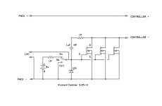
OK, with a bit more thought, here's something that almost does everything.
ZERO drain off. ZERO battery drain on. Super small battery drain during precharge, but only for about a second. Battery would last for the shelf life, or close to it. Since it's battery powered, it could be installed on the positive side by reversing the direction.

To be a bit more conservative during precharge, maybe a 2.2uF would be better, but even at 100v and 10,000uF controller caps, it's about 1A charging current.
Automatic Precharge 3b schematic.jpg

Edit:
I am wrong about the capacitor. I'll have to do some math to get an exact value, but it can actually be quite a bit smaller to get the desired ramp rate. Since the 9v battery supplies the bias on precharge, the ramp rate will be independent of the pack voltage. For higher voltage systems, the precharge time will be longer. I think somewhere around 50V/sec will be good. 2 second charge time on a 100V system.
 
Hey Methods,

Saw these tiny aduino's on kick starter

http://www.kickstarter.com/projects/1608192864/rfduino-iphone-bluetooth-40-arduino-compatible-boa?ref=home_popular

Thought they might give you a semi.

Hooroo
Paul
 
fechter said:
OK, now my turn to attack :twisted:

The HVC breaker is really needed. I would suggest making it a separate unit from the controller disconnect.


The idea was to make this module so that it could act as an HVC breaker between the charger and pack... or it could also act as an LVC breaker as a module between pack voltage and the controller regulator power line. A third application would for it to be in-line with discharge on a 4S pack as an accessory pack - for charging cell phones etc. So yea - I totally agree that we should keep them separate and get the HVC breaker going.

-methods
 
That is a slick circuit. Very thoughtful of you to help out Fechter :)
There are two things that it does not do:

1) It does not cut charge current in the event of HVC... the ol' body diode issue.

2) It does not *latch* the LVC or HVC condition - and that is one of my requirements. If the circuit does not latch then we are at the mercy of the system for whatever oscillation we end up going into. My chips have 1.2 seconds of hysteresis on HVC.. but none on LVC. That means that the LVC would be totally under damped and flying into oscillation. Also - long ago Steve made it clear that he does *not* want any sort of HVC breaker that would be turning the charger on and off, on and off, on and off... once a cell hits 4.25V thats it - we want to shut off and stay off.

-methods

fechter said:
OK, with a bit more thought, here's something that almost does everything.
 
Nice... it is on the firm side of rubbery :wink:

thanks,
-methods


Science Faction said:
Hey Methods,

Saw these tiny aduino's on kick starter

http://www.kickstarter.com/projects/1608192864/rfduino-iphone-bluetooth-40-arduino-compatible-boa?ref=home_popular

Thought they might give you a semi.

Hooroo
Paul
 
Back
Top