APL's DIY axial-flux motor

APL said:
In (d), I'll extend the core, so that the coil turns are distant, and only the face of the core is having an effect, then rotate
the core 90 degrees at a time. Isn't the flux that the PM sees, and used for torque, the same no matter the direction the
core and coil are turned?

Yes it is the same, but since this is a PM motor, only the one part of the winding which is 90° to spin direction will contribute to torque and the other part does nothing. So it does not matter how you twist the core because the sides have same length.
On the pic with the single loop coil you can see the direction on top is vertical (green circles) and on the side it's horizontal or 90° shifted.
 
I'm probably digging myself in deeper and deeper, and shouldn't buck the status quo,.. being a newb and all. It's just that
something doesn't seem quite right.
I guess my point was that end turns do matter, if only a little, in the fact that they are still contributing to the total
magnetic flux of the core, wrong direction or not. The more flux, the more torque.

It was my assumption that the core face represented of all the coils turns as a whole, in the form of a monopole, and that
the 'side' of the turn was not necessarily transferred to the face as such. But I guess thats my fail.

I would have thought that the middle of a core could be round, with a round coil, and the end of the core be square,
or trapezoid, and act the same magnetically in a motor as any other shaped coil. Just weaker, because of distance.

2-Figure3-1.png
 
Moving on. I had hoped to be a bit farther along by now, but a few problems are setting me back. I found out that
this fiberglass board isn't exactly the same thickness throughout. Plus, I designed the core slots in back about a 1/2 mm
to short, and the cores don't quite come together in the middle.

So I chucked the carrier in the lathe, and turned about .015" off the two sides. Using a little plasti-guage I was able to
confirm that they are connecting in the middle. I also drilled some holes for the wire to pass through from side to side.
I know that one wire will pass over the top, between the coils, and another will go through the hole, but other than that,
I'll have to wait and see how it goes. I also finished milling the slots a little longer to accommodate the longer cores.
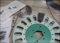
Wire routing..jpg

I had to send off for some tooling that I need to finish putting the standoffs in the cores, so I can bolt them together,
I'm still waiting for that. Meanwhile, I'm trying to figure out exactly how to wind the coils, and get them on the cores.

I'd rather not wind them directly on the cores, because the SMC is so sensitive, and there's a lot of force involved in
manipulating 14 ga wire into shape. But it might come to that anyway.
I can print up some plastic cores to wind the wire on, but then I need to get it back off, and on to the steel cores without
distorting, which would require some kind of glue.
I can also design and print some bobbins to hold the wire, but they would have to be really thin, as I'm not sure there's
any room for them in there as things are. How thin can a print be made?
 
APL said:
I can print up some plastic cores to wind the wire on, but then I need to get it back off,

You can design a small taper angle on the plastic core to ease the removal

APL said:
and on to the steel cores without
distorting, which would require some kind of glue.

Given how thick the wire is I think it should not distort too much. You can probably account for that by printing a very slightly larger or very slightly smaller plastic core (I'm not sure what would work best, probably slightly larger?)

APL said:
I can also design and print some bobbins to hold the wire, but they would have to be really thin, as I'm not sure there's
any room for them in there as things are. How thin can a print be made?

The minimum would be 0.2mm using a 0.2mm nozzle, but that won't be very solid.
 
Thanks Dui, ni shuo de dui, those are really good ideas! I didn't think about a taper, or a larger core. :thumb:

I think I'll try designing a bobbin, and see how that works out, it would really be nice to have something that holds the
coils, and slides on and off. Not sure how it will work in reality, but it's easy enough to try.
It does move the wire farther away from the steel, but I would think that .5mm will be OK, hopefully, it will be strong
enough.

I'll work on making a tapered core too, and see how that works. The coils will be two layers of wire thick, and I'm not sure
if they are going to want to stay completely in shape without a little help. Maybe a few lines of hot glue. I know I've seen
string or pieces of tape used on coils on some motors as well.
 
Another approach might be to use a tapered form made of polyethylene or polypropylene that won't stick to epoxy, then wind the coil with some epoxy, let it cure, and slide it off the form. Silicone grease on the form will help keep it from sticking. Once the coil is cured, it will be like a solid piece.
 
fechter said:
Another approach might be to use a tapered form made of polyethylene or polypropylene that won't stick to epoxy, then wind the coil with some epoxy, let it cure, and slide it off the form. Silicone grease on the form will help keep it from sticking. Once the coil is cured, it will be like a solid piece.
I was thinking a similar thing, but use some inverted kapton tape over the form, so it slides off easy, and is heat resistant and thin, so you can just leave it bonded to whatever potting compound you use. Also adds an extra layer of insulation between the coil and core.
 
After thinking about it for a while, I'm leaning towards the taper idea as well, trying to get my buddies to print up 36
forms is a bit much to ask, and the taper idea requires only a few cores, or forms.

I like the kapton tape , and the epoxy ideas, I'll give them a try. :thumb: I could maybe try a piece of polypropylene bag
as a barrier as well, and use it to pull the coil off when done. I don't think it will stick to anything.

Thanks for the awesome help, I'll get started on designing the tapers and getting them printed. Then a few experiments
are in order. :)
 
As a side note,.. I did finally find a printer. Months and months of searching Craigslist paid off at long last. Its a Monoprice
Maker Pro MK1, 300x300mm bed, and only a few months old. A scream'n deal at only a $100. Has issues though.

Won't print decent at over 100mm, but after looking it over, I can see why. Whoever put it together wasn't very mechanical,
and the bed rails are over 25mm off front to back. Everything else is off as well, and some bolts aren't even tight.
So I need to tear it down and rebuild it square, add some braces, and stabilize the bed,.. which rocks around like a boat
in a lake. Nice printer, just needs help.

Another thing to do, on top of everything else I need to do, along with all the other things I need to do,... some 'ol same.
But eventually I'll be able to stop bothering people, and print my own stuff.
 
APL said:
I like the kapton tape , and the epoxy ideas, I'll give them a try. :thumb: I could maybe try a piece of polypropylene bag
as a barrier as well, and use it to pull the coil off when done. I don't think it will stick to anything.

Plastic bags work well too. Epoxy won't stick to it. You just need the surface of the tapered form to be smooth enough so nothing is interlocking. You could also consider a form made from 3 pieces where the middle piece is tapered and can be pulled out after the epoxy cures allowing clearance to pull out the other two pieces (drawing would be nice here).
 
I know what you mean, it's used in mold making a lot. Definitely worth thinking about. I could print a 3 piece tapered
center core, or maybe just two pice with a slant cut in the middle. Keeping things together while I wound the wire might
be a problem.

I was hoping to wind both coils at once, so I wouldn't have to solder the top crossover wire, but that might be asking too
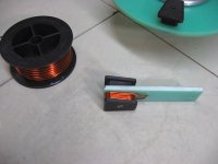
much. I'll need to wind them on a simple form, like this, that I can clamp in a vice, so that theres good access.

10 turns 14ga..jpg

I'm having a little trouble trying to figure out how to add a draft, or taper, to the core rendering I have. It only needs to be
a few degrees, but my cad program doesn't make it easy. The larger programs like Fusion 360 will add it automatically if
wanted.

I'll try messing with it, just have to roll up my sleeves and go for it, otherwise, maybe I can just print a 1mm bigger core
and hand sand it a little. I'm pretty good with the file. :)
 
APL said:
I'm having a little trouble trying to figure out how to add a draft, or taper, to the core rendering I have. It only needs to be
a few degrees, but my cad program doesn't make it easy.
Rather than specifically adding a taper, what about simply selecting all the points (vertices/etc) on the "end" you want to be smaller, then using a "scale" function to make them some factor smaller?
 
After sleeping on it, I'm thinking Fechter's idea might be the way to go, but with a two piece revision. It's easy to do a
slanted split on the core, and the mounting screw should go through both parts to keep things together, along with
the slot in the carrier. Its fairly easy to taper the two ends with the end windings, because theres no brim.

Mentally the idea seems OK, but I might be missing something.

New core. copy.jpg
 
Great, now I can move forward! The coils will be two layers of 5 turns. The conundrum was, one layer with 10 turns
close to the steel, but twice as much weight, (longer core), or two layers of 5 turns for half the weight, but with one
layer 1.5mm farther away from the steel.

Since I'm still not sure how many turns are needed for the best efficiency in this particular set up, I opted for the 2/5.
I figure I might wind up taking some turns off, or adding more, to find that out.

The last motor free spun at 1500 RPM with 10 turns, so I figure twice as many would bring it down to 750 RPM, which
seems more in line for a 400 RPM (in use) motor. But thats just my crazy assumptions again. Like I say,.. I can always
take turns off.

Another assumption is that the answer to how many turns, will show up in the temperature of the motor on a hill test,
given the same conditions. Not the mathematical way to check efficiency, but the results should indicate about the same?.
 
The no-load rpm will be nearly inversely proportional to the number of turns. Most motors run peak efficiency at around 90% of the no-load speed. You might want to consider even more turns.
 
Two layers of five is better than single layer of ten turns needing longer core. Proximity of turn to steel core is insignificant magnetically, according to Ampere's Law. Folks have a hard time believing that.

Regards,
major
 
That's good stuff to know, and it makes me feel a little better. 90 percent of no load, and proximity to steel. I suppose
the proximity breaks down at some point,.. say 10 or more layers out? If not, then why not have a core thats only two
turns deep, and wind up 5 - 10 layers of 2 turns? (sorry, just curious, I'm always trying to lose weight, and that would be
an awesome possibility)

90 percent of no load is a great rule of thumb. It's easier for me to figure no load based on experience from V1, than it is
to guess at, or test efficiency. Although it's a little more difficult since this motor has 18 cores, and the last one had 21.
I'll have to do some think'n.
 
The single layer of 10 coils will provide double the exposed copper surface area for cooling, and more core thermal mass, but at the expense of a larger/heavier motor. It really depends on your design goals, but for a mobile motor, efficiency and power density are probably your primary goals, and a more compact coil better achieves that.
 
The balancing game gets clearer with time. I choose a slot/pole count number for a general desired RPM range, which
gives a certain slot and core width. The more turns or layers wanted reduces the core size, invites saturation, and less
cooling. Thanks for making that clear. :thumb:

A lesser slot/pole count might gain more room, but will run faster, which leads to a transmission, and we gain back the
weight and complexity. A higher count leads to more copper and hysteresis.

It may be that I've chosen the wrong S/P count for this app., time will tell, but being a mid drive I still have some gearing
options, so thats a good thing. DD hub motors seem to be the true victims of the balancing act.

Luckily I think I still have some wiggle room, I'll take Fechter's advice and try to add some more turns, if theres room.
It's more difficult to add windings after the fact, with splicing and soldering, but very easy to take turns off if needed.

Hopefully I can get close to the desired RPM range, but if not,.. then I'll just have to ride it 50 miles per hour! :)
 
What you do is to wind one coil: use any wire, any number of turns, spin motor to measured rpm, measure voltage out, convert that to kV given your delta or wye, parallell/half parallell etc connections. Scale turns for final configuration with the kV relationship you need.

Takes out all the guesswork :wink:
You’ll be sorry if you miss your desired rpm and haven’t done this and you can evaluate what current you can use by the chosen coil resistance and balance this vs kV
 
Sounds like a good plan. Could save me from wasting a lot of copper wire and time. It would be nice to get a preview.
It will also allow me to adjust things a little closer to the correct air gap, without having all the cores in place.

Once I get the 3D prints done, I'll wind up a core set, do some voltage test's, and see where things sit. I'll also see how
many turns, or layers, I can add before they hit the next coil, so I'll know the maximum number of turns possible for this
gauge wire.
 
Back
Top