Common pack design mistakes, how to avoid?

Allex

100 MW
Joined
Dec 5, 2011
Messages
4,232
Location
Stockholm, Sweden
[this thread was split off from another thread where a poster described issues with their DIY spot-weld pack, pics revealed a few poorly-chosen amp-flow paths]

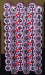
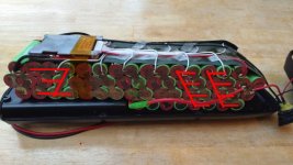
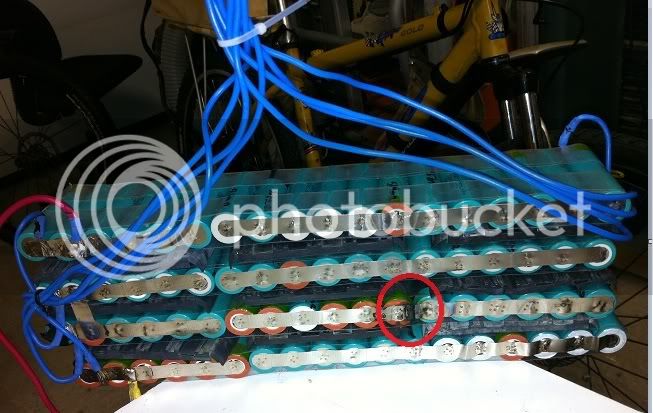
Boy, we should really have a thread on how to not build a battery. We have a great one on spot welding(https://endless-sphere.com/forums/viewtopic.php?f=14&t=68005) but we don't have Ultimate thread on how to actually design a pack so you can get the best current flow and avoid burned nickel, getting unnecessary voltage sag (unbalanced under load because of the wrong design) and dead cells as a result like in the below pictures. Everybody can build batteries but only 5% of the guys actually doing it right.
file.php


xxxxxxxxxxxxxxxx

moderator edit to add tip from this thread: hot-glued cells can be separated by using isopropyl alcohol on a cotton-tipped swab. https://endless-sphere.com/forums/viewtopic.php?f=14&t=84412&start=25#p1237470

also: nickel-plated copper bus bars are a good option to make the series connections between paralleled sub-packs. https://endless-sphere.com/forums/viewtopic.php?f=14&t=60364&start=25#p1235640

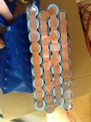
Here is an example of badly designed pack from china:
file.php

"The serial nickel conductors amount are not enough, but the main lead points are even worse.

Where the main battery wires are soldered, it that spots the nickel are completely in overcurrent. I don't see if they soldered more layers, in case that no, that points will heat the most in the battery, just check it."
Read more on why:
https://endless-sphere.com/forums/viewtopic.php?f=14&t=57291&start=550#p1034920
 
..just as an example of a good pack design. ..( a stripped commercial pack..Bosch i believe)
note the continuous "buss bar" type strip between cell groups.
also the use of plastic cell holders to retain the cells , rather than glue or relying on the welds.
the only welds are those attaching the strip to the cells
IMG_20150915_152724_zpslsy3y2i4.jpg
 
I believe "hot gluing" between the cells is not good for many reasons, and doing so leaves the quality of work, the type of glue, and quantity of glue up to the individual builder. Over time I am leaning towards the plastic cell separators, as shown in the pic above. Vibration can cause two adjoining cells to short, and although both shorted cells would be negative to negative (the outer metal shell of every 18650 is the negative anode), it can short from one P-group to the next, instead of forcing the current to go through the bus strips.

Also, nothing wrong with a square pattern to the separators, but I just like the "honeycomb" pattern on these...
 
Last edited:
Another advantage of the "skeleton" holders shown above is that not being full length of the cell, they leave a air gap all round the cell..probably only 1 mm between cells..but enough to alow good air flow allowing cooling of the cells in the middle of the pack. Hot glue will give you the closest packing of cells, but in doing so, tends to shut off much of that air flow path.
 
LIQUID NAILS

I've never liked hot glue - far too weak. Planning to build a battery pack glued together with liquid nails. Should be a lot stronger than hot glue. Any concerns?
 
Hillhater said:
..just as an example of a good pack design. ..( a stripped commercial pack..Bosch i believe)
note the continuous "buss bar" type strip between cell groups.
also the use of plastic cell holders to retain the cells , rather than glue or relying on the welds.
the only welds are those attaching the strip to the cells
IMG_20150915_152724_zpslsy3y2i4.jpg

It looks nice, but I still find a single set of spot welds to be unacceptable. 4 welds should be the minimum.

LiFeCycle said:
LIQUID NAILS

I've never liked hot glue - far too weak. Planning to build a battery pack glued together with liquid nails. Should be a lot stronger than hot glue. Any concerns?

I don't like hot glue either. Quick Grip glue is all I use. I highly recommend it. It's slightly flexible, low odor, dries to a usable strength in a few hours and its cheap. Much stronger than hot glue as well.
 
Hillhater said:
..just as an example of a good pack design. ..( a stripped commercial pack..Bosch i believe)
note the continuous "buss bar" type strip between cell groups.
also the use of plastic cell holders to retain the cells , rather than glue or relying on the welds.
the only welds are those attaching the strip to the cells
IMG_20150915_152724_zpslsy3y2i4.jpg

I actually disagree that this design is an example of a good layout, it's perhaps adequate and very easily manufactured. It suffers from the same issues as some of the other poor examples that sparked this thread, there's only a single connection that carries all of the current between the parallel cell groupings. The custom plastic casing is great with pretty good fill rates, but the connectivity isn't something to emulate on a high power build.

The important part of achieving low pack resistance is the series connectivity - NOT the parallel groups. The reality is this simply doesn't matter very much if the effective resistance is low enough that the losses are immaterial with what the pack is designed to discharge. At legal ebike power levels this isn't much of a factor, but on the hotrods that are pushing serious amps it can make a big difference. On my first 20s10p pack I made from LG HE4's I went with a hot glue build with a dense layout. I ran one strip to parallel connect every cell, then connected every cell to its next cell in series with 0.3mm nickel. Effectively I had 10x 0.3mm nickel strips connecting my series groups. Terminated with double layer of 0.3mm nickel and 8ga wire.

Some people have put a ridiculous amount of effort into achieving ideal current sharing between cells - this simply doesn't matter if the resistance of the terminated parallel groups is low enough. There will be almost no potential difference between any two cells in a group if well terminated.

On the pack I'm building now I've changed it up slightly, I'm using a CNC cut honeycomb of high temperature lightweight foam card for complete cell isolation and I'm terminating the pack with cut sheet of 0.2mm nickel covering each parallel grouping and its next series group. Once all the spot welding is done I'll be encapsulating the ends of the pack in some epoxy for some serious ruggedness while retaining an airgap for 75% of the cells length which should make a big difference to cooling.
 
I still think the very common stackable 18650 holder is a good all around solution.
These combined with nickelstrips punched to fit over two cellrows, makes for good series connections.
It is also alot faster to build that dealing with "single strand" strips.

The end connections will need some multi connection point wire harness depending on if the pack is built out of many P's, and current transfer needs.
The cellholders are not as compact as glued packs, but offer a rigid structure with 90 degree corners, with airgaps around all cells.

I usually design my batterypack layout before I build where it should go on a custom bikeframe.
That is because this is alot easier to get right than having to build a customized pack shape.
 
This is my first pack with cellholders and i must say it is much easier than gluing it all together. Also the "traintrack" strips are great to work with.
That is if you have the space for it all.
Only thing i am struggling with at the moment is the series connections between my 3 pack.
 

Attachments

  • IMG_20161022_101152 (Medium).jpg
    IMG_20161022_101152 (Medium).jpg
    119.8 KB · Views: 23,500
Hillhater said:
..just as an example of a good pack design. ..( a stripped commercial pack..Bosch i believe)
note the continuous "buss bar" type strip between cell groups.
also the use of plastic cell holders to retain the cells , rather than glue or relying on the welds.
the only welds are those attaching the strip to the cells
IMG_20150915_152724_zpslsy3y2i4.jpg

Lets stick on how to improve packs in this thread and how do design the pack for best current flow, talks about glue/holders and other stuff please keep it in other threads like DIY welding: https://endless-sphere.com/forums/viewtopic.php?f=14&t=68005

Here is the same Bosch pack and how it can be improved. We put 4 cells in a row instead of 4 cells in a square group. This way we have a shorter bus that goes from Neg to Pos and we make 4 connections in total - one per cell instead of one for all 4 cells. Shorter bus and and more series connections gives you less resistance=less voltage sag=less heat that goes to the air instead of your controller/motor. Note that I only have one strip that connect all the cells in same group. This is because you don't need more than one, there is no current that flows between cells in the same P-group so you dont need to add a second one. Now for this particular Bosch it may be totally ok with such design, because the whole power system is only 250W and you probably only see 10-15A tops on the original Nickel bus bar. But for those who runs systems that Are capable of more than 15A the layout of the cells/nickel start to get crucial.
 
Here is another pack with bad connection, there is 10 cells in parallell but they only have two series connections to the next group.
24dk8l1.jpg

This means that those two bus bars will be stressed at high currents and the cells at the connection will be drained faster then those in the middle, this means premature failure of those cells close two the series connections. Again this design is ok if you will use 1-5A current but anything more than that you need to makes some modifications. Luckily the cell arrangement is optimal so we only need to add series connections, this will give us the perfect current distribution across the cells:
24dk8l1 mod.jpg

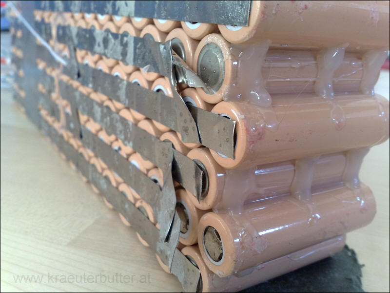
Here is a China pack with only two nickel connections!
Zellen_verklebt_26012009153.jpg

I dont know why they do it, maybe to save on the nickel? If thats an issue they could've skipped the second long strip(because you don't need it) and add 7 more fot the series connection.

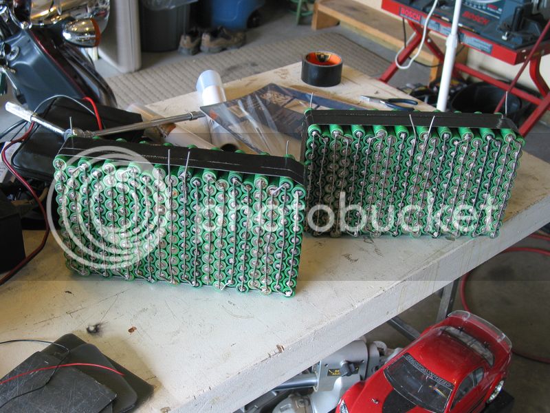
Here is another one, you think you can complete this pack without my help? :)
84v_30ah_konion1.jpg
 
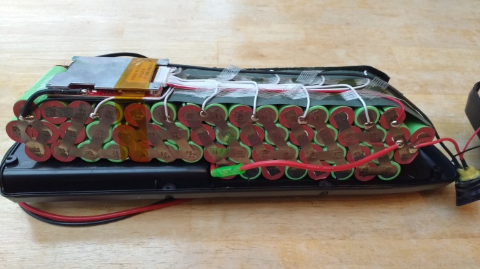
Here is a popular shark pack 52V(I don't know why everybody calls it 52 when it is really a 50V pack 3,6*14)14s4p made in china:
img_20151222_0824557521.jpg


They typically rate these for 30A current and sell them for your BBSHD system. What is wrong with it?
Again, they only have two nickel strips to connect the series. one strip is good for about 10A so when you push 30A the strip gets hot, so those precious watt-hours goes into heating up nickel instead of going to your drive system. Another thing is that the current does not flow equally across the cells. The path is short where they place the series strip but 2x longer where they did not. This means more stress on first cells.
Again, skip the second parallell strip and ad more series, the improvements are in red:
 

Attachments

  • img_20151222_0824557521.jpg
    img_20151222_0824557521.jpg
    51.3 KB · Views: 23,505
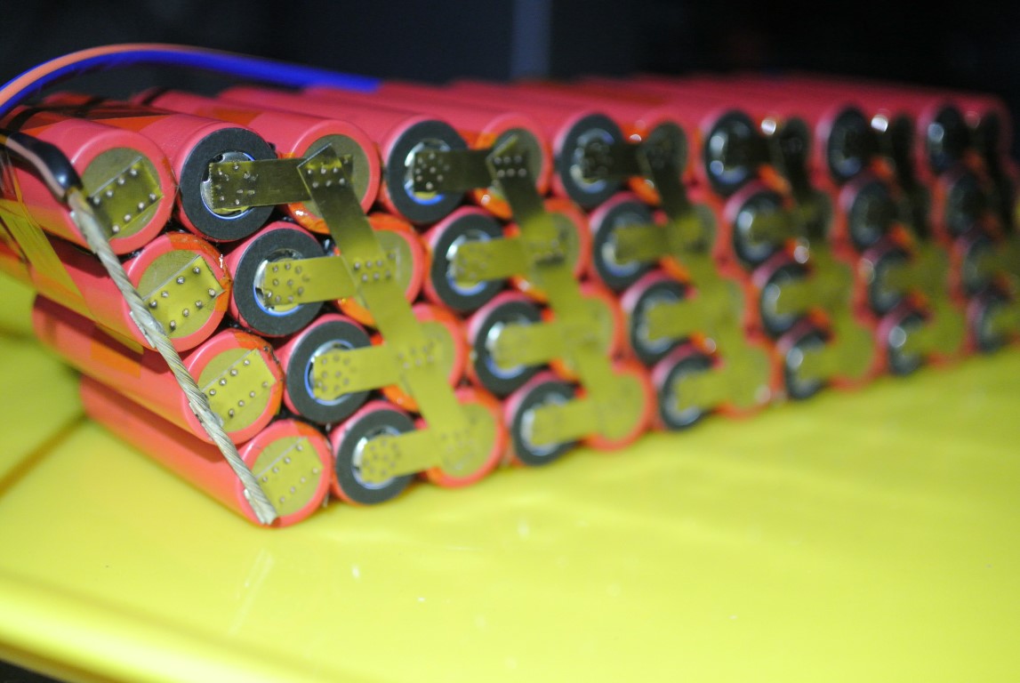
Good connection, note that they only have one parallell strip:
IMG_2169.JPG


Optimal design, every single cell have a connection to the next group, same here, only one bus bar for the P-group
IMG_2707.JPG


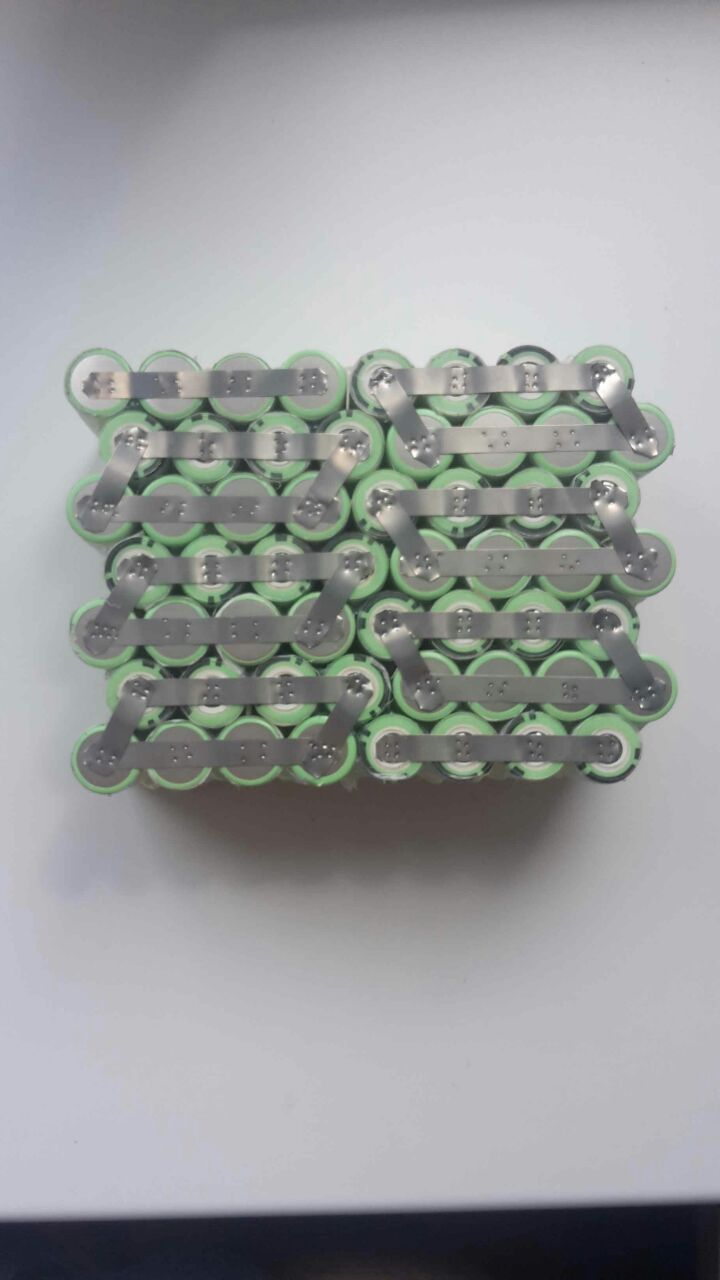
Here is the same cell layout but a bad layout of the nickel, can you tell why after all my pictures? :)
1e0h8zp.jpeg

1ikyj8d.jpeg
 
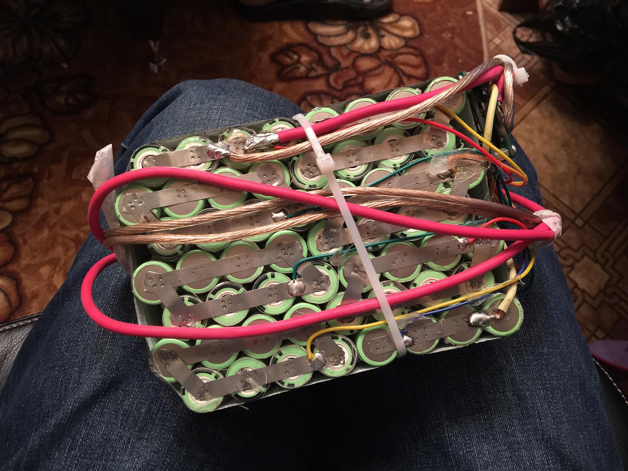
I copied maddin's design when I built my 24s15p Konion pack early last year. I think this design of connection is the best home made style. Mine was a hot glue design that worked well until I had a bad row and had to remove it.....that sucked. My next build will have the same layout but may just glue the individual rows together but not glue the rows to one another. I used .02 with 10 gauge throughout but will go 6 or 8 next time.

What I made works perfect except pulling almost 200 amps gets me too much voltage sag on my downsized 20s15p pack. 150 amps all day long though.

Tom
 

Attachments

  • IMG_0575.JPG
    IMG_0575.JPG
    83.1 KB · Views: 23,490
  • IMG_0576.JPG
    IMG_0576.JPG
    48.6 KB · Views: 23,487
  • IMG_0574.JPG
    IMG_0574.JPG
    64.3 KB · Views: 23,490
  • IMG_0573.JPG
    IMG_0573.JPG
    68.1 KB · Views: 23,486
Great design litespeed, the best actually, but very time consuming and hard to weld :)
Next thing to talk about is how to terminate the ends in the best way, what is the optimal way of adding negative and positive wires to a pack to keep the an even current flow all the way to the wire?
 
Allex said:
Great design litespeed, the best actually, but very time consuming and hard to weld :)
Next thing to talk about is how to terminate the ends in the best way, what is the optimal way of adding negative and positive wires to a pack to keep the an even current flow all the way to the wire?


NFkifIF.jpg


this is what i like to do. it's just a low power pack for bbs02 so 12ga soaked in solder should be sufficient. pre-soldered nickel tabs, then finally welded onto the cells
 
Very nice pack OC!
Yes it is important(at least when it comes to high drain packs) to have a thick bus on the and of the pack and it is a very good adea to have it along ALL of the cells at the end. Having a good design of the pack and then finish it up with a soldering blob at one end, like in this one below, can be a negative experience in the end.
1.jpg
 
Allex said:
Here is another one, you think you can complete this pack without my help? :)
84v_30ah_konion1.jpg

LOL. This was mine a few years ago. Joined with silicon beads and soldered. Many solder connections failed after a short while, I am lucky this did not cause any serious damage to my ride or property. I learned a few things since then. I hope. :) I was thinking of going with something like this for a high power application with stuff that can be sourced easily. That is if I could afford to buy over 600 cells for my application. https://endless-sphere.com/forums/viewtopic.php?f=14&t=68005&start=325#p1165636
Instead of having the positive and negative terminals stick up like in the linked post above, I was thinking of bending the Copper sheets over a 3/8'' block of GPO3 that has a couple blind nuts in it to line up with holes in the Copper sheets. That way each module could be connected in series using large cables with lugs or big bus bars.
 
Allex said:
Great design litespeed, the best actually, but very time consuming and hard to weld :)
Next thing to talk about is how to terminate the ends in the best way, what is the optimal way of adding negative and positive wires to a pack to keep the an even current flow all the way to the wire?


Hard to tell in the pictures but I used the same width of nickel as the rest of the connections and folded it over and soldered my 10 g wires to those. Even with my monster 150 watt 3/4" tip soldering iron it was all I could do just to heat 2" of wire to that nickel.

Again, Maddin gets the credit and I got a great pack.

Tom


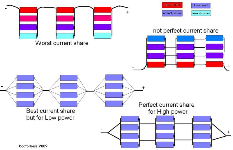
Many years ago in a undergrad tutorial we worked out the "correct" way to parallel things like battery's and stuff. and attached was the correct way. If you have a lot of things (resistors or battery's) in parallel then feed in from one side and out from the other. That way all of the battery's have equal length leads. Of course if you just go "massive" then it doesn't really matter.

Regards Bob
 
This is great info. Thanks Allex.

If i look at the efficiency chart for nickel:

0,15mm*7mm: 4,7Amp
Midi-e: max 120A from battery
120Amp/16P = 7,5 Amp per cell
My strips: 0,15mm
So i should layer 2 strips for best performance ?
 
Some packs are lacking proper protection between the positive and tab connection. These scares me with 18650 packs with so many connections. Still all it takes is one short.
 
I would like to try and build an 18650 mini luna style pack, I currently run lipo as still learning and plenty of examples to follow.

I have a welder in the making can someone post the best configuration for a 14s2p. Many thanks in advance.
 
Back
Top