Connecting a Cycle Analyst to a Castle Creations controller

ElliottE

100 mW
Joined
Apr 27, 2012
Messages
36
Location
Spokane, WA
Hello everyone,

I'm in the final stages of assembling my second e-bike prototype, and I'm currently trying to get everything all wired up. This design uses a Cycle Analyst V3 with a Grin Tech shunt, and I want to connect the shunt to a Castle Creations HV160 controller. The Grin Tech shunt has three small wires that (I believe) are intended to connect to the controller, these are green, yellow and black. The Castle Creations HV160 controller has three small wires that (I believe) are intended to connect to the shunt, those wires are orange, red and brown.

My best guess at the moment is to connect it as follows, and I will include what I think these signals are:

Green > Orange (Control / Throttle signal)

Yellow > Red (+5 volts)

Black > Brown (Ground)

If anyone out there has any information regarding this, your input would be greatly appreciated.

Elliott
 
I've been searching repeatedly, unfortunately I'm not finding any threads that address my particular question. If anyone would be kind enough to provide a link, it would be greatly appreciated, apparently my search-fu is weak.
 
Hello amberwolf,

Thank you for those search links, I'm checking those out now. In the meantime, being as a picture is worth a thousand words and all that, here's some pics of what I'm working with:

10373683_489003384570476_1647732753109329803_n.jpg

Cycle Analyst V3

10348287_489003534570461_5222415437722857662_n.jpg

Grin Tech shunt

10364017_489003464570468_1565145577368097940_n.jpg

Castle Creations HV160

10631093_489010634569751_6492132230908496636_o.jpg

Another piece of the puzzle. This is a CastleLink USB connector, connected in such a manner that it communicates with the controller. Note the wires and the corresponding signals indicated on the CastleLink.

10599226_489003594570455_6877338615721485700_n.jpg

Prototypes 1 and 2 (prototype 1 is in the background)

https://www.youtube.com/watch?v=I-5eys9y2bo

Here's a link to a YouTube video of prototype #1 being taken out for a ride up and down a good-sized hill.
 
ElliottE said:
This design uses a Cycle Analyst V3 with a Grin Tech shunt, and I want to connect the shunt to a Castle Creations HV160 controller. The Grin Tech shunt has three small wires that (I believe) are intended to connect to the controller, these are green, yellow and black. The Castle Creations HV160 controller has three small wires that (I believe) are intended to connect to the shunt, those wires are orange, red and brown.

My best guess at the moment is to connect it as follows, and I will include what I think these signals are:

Green > Orange (Control / Throttle signal)
Yellow > Red (+5 volts)
Black > Brown (Ground)
I do not have specific experience with your ESC - however:

Presumably you are powering the ESC via the CA-SHUNT 'CTRLR' power leads.

As I understand things, the CC EDGE HV 160 has no internal BEC and requires an external BEC for ESC operation (specifically the red receiver wire must be tied to the BEC). You can verify this by powering the ESC via the shunt and using a DMM to measure the voltage on the red receiver/USB ESC cable. You should not find +5v there (no BEC). The brown receiver cable wire and primary black ESC power lead should both be connected within the ESC and so be at Gnd potential.


Based on that, you will need to provide +5v BEC functionality via the CA3 by re-wiring the CA PCB and re-purposing the CA3-SHUNT breakout cable yellow wire according to Section 4.2.1.5 "Installation with RC Electronic Speed Controller (Normal Mode)" of the Guide.

Having done that, your proposed hookup looks exactly right.

The Guide is light on description for ESC setup, but mentions relevant settings as they are needed during the installation section. In particular, you will need to ThrO->OutptMode = R/C Pulse. Section 5.3 "Ebrakes" also mentions a possible adjustment to ThrO->BrakeOut if your ESC balks at zero-width PWM on the throttle lead.
 
Just FYI to anyone interested, I now have my CA V3 updated and working with my controller and motor, just got the motor to light up and spin. Next step is to do a couple of more things on the e-bike, and then I can install the motor and take my first test ride. I'll post pictures when I do.

Elliott
 
CA/ESC Kill or ON/OFF Switch

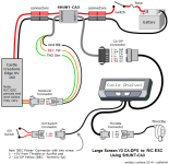
This Castle Creations ESC needs an external +5V supply (BEC - Battery Eliminator Circuit) to power the on-board logic. The present CA V3 Guide provides the same BEC wiring instructions as discussed above.

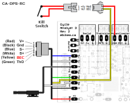
But - thinking about this, it occurred to me that this is not unlike the situation with Xie Chang and other ebike controllers that possess an 'ignition' wire that must be connected to Vbatt+ to power up the controller. This low current wire affords a handy ON/OFF switch and/or kill switch. Internally, this ignition wire is simply tied to Vin of a +5V regulator that powers the controller logic - the equivalent of the external ESC BEC hook-up. This same capability should be able to be realized with ESCs requiring an external BEC by simply switching the BEC connection.

Here's how this might be done:

CA-BecWithKill2.png
CaV3-RcEscHookup.png
This is untried - I don't have one of there ESCs to inspect, but it seems extremely unlikely that CC has anything other than a conventional FET phase driver etc. There is no mention in the CC literature of any restrictions on the order in which the ESC power and BEC wiring is hooked up. I have an email in with Castle Creations about this, but no words yet about any possible issues or if there are any parasitic resistors that might cause a minor current drain if the controller was switched off this way. Anyhow - you might give this a go if you want to add a kill switch to your CA/ESC hookup.

Please PM if you verify this and I will add it to the CA V3 Guide. :D
 
I'm working in my first project and connected a castle creations hv80 as described in the CaV3-RcEscHookup.png picture. The CA works and the throttle seems to work too since I see the throttle going up and down on the CA display.
The problem is there is a red LED blinking on the controller and the motor doesn't run.
Anybody can give me some advice. Do I need to set up the controller or something like this?
Thanks
 
If the light is blinking it is probably in a pattern that you would have to check the controller manual for to find the error code.
 
First, you must set ThrO->OutputMode = 'Rc Pulse'.
This replaces the normal ebike throttle voltage signal with a PWM waveform like that provided by R/C servo receivers/testers.

Next, Castle Controllers throw a throttle fault if the input pulse stream goes away or has a pulse width less than about 0.4ms (0.4ms is an empirical value offered by CA users - CC actually has no specification for this minimum width, so that figure may vary somewhat.) The out-of-box CA default value is 0ms (no pulse output) which undoubtedly accounts for your controller fault.

The CA has ThrO->BrakeOut=0 by default. In the earlier 'preliminary' CA 3.0 firmware releases (e.g. up to 3.0p11), this voltage (in your case period in ms) is what the CA outputs when brakes are applied. In those cases, it was necessary only to set BrakeOut >0.5 ms so that on braking, the CA would reduce but not entirely remove the pulse stream.

Unfortunately, the new proportional regen feature released in CA 3.0 can cause problems for R/C installations. In 3.0, hitting the ebrakes shifts the throttle output to BrakeOut voltage/period as before, but now opening the throttle with the ebrakes applied causes the Throttle Out signal to decline from BrakeOut to 0 as the throttle goes from ZERO to WOT. This controls proportional regen for Grin controllers, is ignored by all other ebike controllers, but can cause R/C controllers to throw an throttle fault near WOT (maximum regen braking).

There are some workarounds for this, but they really belong in the CA V3 Beta thread not here.
Here's two quickie approaches instead:

  • Verify that:
    • ThrO->OutputMode = 'Rc Pulse'
      ThrO->BrakeOut = 0.4ms or more but less than ThrO->MinOut
    This should get your controller working as long as you don't got WOT with the brakes applied.

  • OR - Re-flash your CA with new 3.1 beta firmware which allows you to disable proportional regen. Here you make similar settings:
    • ThrO->OutputMode = 'Rc Pulse'
      EBk->BrakeOut = 0.4ms or more but less than ThrO->MinOut
      EBk->PropRegen = Disabled
    With proportional regen disabled, the CA simply outputs BrakeOut and does not vary it with the throttle setting - behavior identical to the older 3.0p11 release.
Hope this helps... :D
 
Set up
Thr0>OutputMode=rc pulse
Thro>brakeOut=0.4
Thro>MinOut=0.3

But the LED is still blinking and the motor is not running.
Any other sugestion?
Thanks
 
Not until you look up the fault code in the CC manual...

You've set the throttle ZERO pulse width (Thro>MinOut=0.3) smaller than the minimum that the controller considers a fault (?).
That means that when you turn on the bike with the throttle at ZERO you are guaranteed to get a controller input fault.
 
I'm messing with a CA3 and an RC ESC that also requires BEC power. Using the above diagram as a guide I connected the yellow CA3 wire to the 5v pot pad on the CA3 board. Im using an external grin shunt with the pass through throttle ground and yellow wire.

A strange observation is that the CA3 screen goes blank if I connect the Throttle to the ESC after the CA3 is powered. If I make the throttle connection first then connect the CA3 it works fine. The screen stays powered it just goes to all solid blocks instead of characters.

Initially I had powered the Ca3 by plugging in the 6pin connector to the shunt. I thin verified the 5v present on my yellow wire and connected it to the ESC throttle plug. The screen immediately went blank and I freaked out figuring I had cooked something. Upon reconnecting the CA3 plug It booted and worked fine.
 
Back
Top