Cheap FOCer (VESC 4.12 based design)

shaman

1 kW
Joined
Dec 10, 2018
Messages
343
Location
Fort Worth, TX, USA
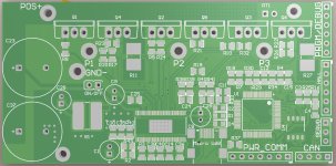
View attachment 2
angled
View attachment 1
bottom
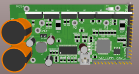
vesc top.png
top

Hey there. I’m rehashing the VESC into a cheaper 2 layer version with external FETs. I’ll call it the Cheap VESC for now. You may notice it resembles the generic ebike controllers that you can find on ebay/aliexpress. This is a version that would probably cater more toward the ebike/e-scooter community but probably could still fit just fine on a skateboard. The primary goal here was to make a version of the VESC that is cheaper to create by reducing the original design to 2 layers (check out JLC PCB for super-duper cheap 2 layer boards) and reduce BOM cost a little. The secondary goal was simply to improve my PCB layout and design skills. I still haven’t finalized the design but I would say I am at least 95% done with only a few minor problems to tidy up. If after reading all of this anyone has any suggested improvements to the current or future designs, please feel free to respectfully make them in this thread. Note that this is my most complex board design for me so far with my previous experience being only with simple audio effect boards and circuits.

Cheap VESC

Advantages

  • Lower build and BOM cost
  • TO-220 FETs allow for big heat sink attachment for excellent thermal performance
  • SMD components no smaller than 0805 make hand assembly practical
  • Added ON/OFF capability to turn off control circuitry when controller is not in use. A simple mechanical switch will achieve this when connected to the “ON/OFF” 2-pin header.

Disadvantages

  • Larger than original VESC. Cheap VESC is 45mm x 92mm
  • Higher profile with TO-220 package FETs
  • Additional assembly steps to beef up high-current traces. 2 layers of 1oz copper can’t handle the current flowing through during operation. Assembler will have to apply wire/solder wick/bus bar to the exposed Power, Ground, and Phase traces that you can see in the “bottom” image.

Potential features of Future Versions

  • Implementing DRV8353 for higher voltage operation (I estimate at least 20s capable). Will need stable version of VESC 6 firmware/software for the 3 phase current sensing and stuff.
  • On-board circuitry for no-spark connection
  • On-board Bluetooth capability for interface with Open Source Android app for the VESC
  • I may create a 12 MOSFET version with the FETs in parallel for even greater power.
    Notes

I intend to test the design rather thoroughly after I get a version assembled. I intend to power a motor under load with different loads while observing temperature with a thermal camera. I will test other features of the design to ensure quality. Because of all this, it will be some time before I release the design files. I don’t want to give the community a broken thing.
 
@SlowCo

Thanks! Also, everyone feel free to make suggestions on the design. I'm a bit of a noob on boards more complex than an OP AMP or two so I'm sure there are some mistakes or non-ideal qualities.
 
You probably want to use some of the improvements from 6.6, like three shunt resistors for better FOC.
Really appreciate the effort and sharing it here.
I'm thinking about trying myself on a VESC for the BBSHD in the future. With good FOC and 14S support but I'll have to wait until somebody comes up with a good schematic for this as not even the new 6.6 can do 14S ...
And I think it'd be much easier to fit this into a case (with proper heatsinking) if the FETs are at the end of the PCB.
 
@BotoXbz

Yeah the 3 shunt capability is definitely going to be in a future version most likely with the new DRV8353. I'm sticking with the old version for now as there's plenty of support for it, examples of it working with good results, and I need some experience before I really get into it. The DRV8353 can drive FETs with up to 100V supply so that should be able to handle 14s or more. I sort of need the FETs in this particular arrangement to fit in my particular ride plus it could probably slide right into one of those aluminum enclosures from those chinese controllers. Are you saying they would be better at the end where most of the connectors currently are?
 
The FETs are fine where they are but there might be a little bit too much PCB on the edge so that you will have to bend them a lot to make contact to an even surface (enclosure / heatsink).
The DRV8353 has less current capability in comparison to the DRV8302. I'm not sure how much gate current is really needed but I suppose you could always add two of the DRV8353 if that becomes a problem.
 
@BotoXbz

I see what you're saying. The idea is that one will use an aluminum bar the same thickness (or slightly greater) as the space between the FETs and the edge of the PCB. This will then create a flush surface for one to then put into an enclosure. This is also how the chinese controllers do it. Also, I confirmed with the engineers from TI who support the DRV8353 that it can drive 6 or even 12 FETs as long as the gate charge is small enough. Current needed to drive FETs is depend on the gate charge and I will just have to choose my FETs carefully.
 
shaman said:
@BotoXbz

I see what you're saying. The idea is that one will use an aluminum bar the same thickness (or slightly greater) as the space between the FETs and the edge of the PCB. This will then create a flush surface for one to then put into an enclosure. This is also how the chinese controllers do it. Also, I confirmed with the engineers from TI who support the DRV8353 that it can drive 6 or even 12 FETs as long as the gate charge is small enough. Current needed to drive FETs is depend on the gate charge and I will just have to choose my FETs carefully.

Yes: this design screams for an alu box. Maybe you can design it so it matches one of the common sizes of extruded aluminium boxes found on ebay / aliexpress ?
 
@qwerkus

Yes I can see if that's feasible. I have one of those common extruded aluminum enclosures in the garage I can take a look at. One might have to drill different holes in the enclosure to mount this controller though. The dimensions of the controller itself should allow for a relatively easy drop in replacement.
 
BotoXbz said:
You probably want to use some of the improvements from 6.6, like three shunt resistors for better FOC.
Really appreciate the effort and sharing it here.
I'm thinking about trying myself on a VESC for the BBSHD in the future. With good FOC and 14S support but I'll have to wait until somebody comes up with a good schematic for this as not even the new 6.6 can do 14S ...
And I think it'd be much easier to fit this into a case (with proper heatsinking) if the FETs are at the end of the PCB.

Isnt't the version 6 rated for 60V ?
 
qwerkus said:
BotoXbz said:
You probably want to use some of the improvements from 6.6, like three shunt resistors for better FOC.
Really appreciate the effort and sharing it here.
I'm thinking about trying myself on a VESC for the BBSHD in the future. With good FOC and 14S support but I'll have to wait until somebody comes up with a good schematic for this as not even the new 6.6 can do 14S ...
And I think it'd be much easier to fit this into a case (with proper heatsinking) if the FETs are at the end of the PCB.

Isnt't the version 6 rated for 60V ?
As far as I know it's the same 60V rating as the version 4.12, the voltage spikes will kill it :D
I think 13S will work with no regen but a full 14S would already kill the controller with FOC....
60V theoretically lol
 
shaman said:
@qwerkus

Yes I can see if that's feasible. I have one of those common extruded aluminum enclosures in the garage I can take a look at. One might have to drill different holes in the enclosure to mount this controller though. The dimensions of the controller itself should allow for a relatively easy drop in replacement.

Awesome - count me in for testing. I always wanted to try VESC with regen on an ebike. Drilling new holes is not a problem. What might be is proper sealing. Never seen a KT-style controller stay completely dry.
Once you have finalized the size, I can help you find o-ring sealed side caps for the aluminium box.

Btw, I love the on/off switch. But rather than a BT / android app, I'd go for a regular display. The team around casainho has already rewritten most of the code to interface with cheap Kingmeter displays; it's just a matter of making it compatible with VESC uart. Maybe a job for me
 
qwerkus said:
Awesome - count me in for testing. I always wanted to try VESC with regen on an ebike. Drilling new holes is not a problem. What might be is proper sealing. Never seen a KT-style controller stay completely dry.
Once you have finalized the size, I can help you find o-ring sealed side caps for the aluminium box.

Cool. I'm also not above just slathering some RTV silicone on the seams. I'll also investigate watertight connectors for connecting power and signals to the enclosure. All that in good time though. I gotta make sure the controller will work decent first.
 
qwerkus said:
Awesome - count me in for testing. I always wanted to try VESC with regen on an ebike. Drilling new holes is not a problem. What might be is proper sealing. Never seen a KT-style controller stay completely dry.
Once you have finalized the size, I can help you find o-ring sealed side caps for the aluminium box.

Do you know a good place to look for those sealed caps?

I'm also working on custom VESC hardware. I've already bought the aluminum enclosures, but the caps they came with are very basic. I've not had any luck looking for alternate caps, and I was thinking I would have to buy silicone sheets to cut to size for sealing the end caps.
 
Awesome. 12FET should be the ultimate goal.
This could become the ultimate controller for us fairly easily, if the design can scale to 100A capability.
Bonus points if you can crank up the peak voltage handling to 96V.

Don't get stuck on the TO-200 package though unless you have determined that the best of FETs comes in that size. My knowledge of FETs is a bit dated but i remember a period of time where the lowest RDSon figures happened in other packages.

Wish you the best with this!
 
neptronix said:
Awesome. 12FET should be the ultimate goal.
This could become the ultimate controller for us fairly easily, if the design can scale to 100A capability.
Bonus points if you can crank up the peak voltage handling to 96V.

Don't get stuck on the TO-200 package though unless you have determined that the best of FETs comes in that size. My knowledge of FETs is a bit dated but i remember a period of time where the lowest RDSon figures happened in other packages.

Wish you the best with this!

12FET is what I'm working on. I looked at TO-247 FETs, you can certainly find them with lower RDSon, but when you compare the costs you get better performance by doubling up TO-220 FETs.
 
Ahh.. that makes sense.
 
@neptronix

Thanks for the good wishes! The Rds on of TO-220 FETs these days can be really low. So low that the silicon chip inside isn't even the limiting factor anymore for max current, the package itself is. If using the right FETS then the 12 FET configuration could potentially deliver 100A, its just a matter of how long. My guess would be that 100A wouldn't be a continuous rating but could probably be sustained for a minute or two. I would say that 96V would be too high for the proposed future build with the DRV8353. 96V doesn't leave enough headroom for high-voltage transients with the 100V ceiling. I'd say the DRV8353 version could safely handle 84V(20s). Handling higher voltages would probably have to be achieved by separate gate drivers and current sense solutions.
 
Wanted mention the BESC here -->https://vesc-project.com/node/655. This is a high-powered version of the VESC currently under way with a 150V 150A rating. My design isn't in the same league of power as this. Check out the BESC if your interested in a higher power controller.
 
Addy said:
qwerkus said:
Awesome - count me in for testing. I always wanted to try VESC with regen on an ebike. Drilling new holes is not a problem. What might be is proper sealing. Never seen a KT-style controller stay completely dry.
Once you have finalized the size, I can help you find o-ring sealed side caps for the aluminium box.

Do you know a good place to look for those sealed caps?

I'm also working on custom VESC hardware. I've already bought the aluminum enclosures, but the caps they came with are very basic. I've not had any luck looking for alternate caps, and I was thinking I would have to buy silicone sheets to cut to size for sealing the end caps.

How many? You need to stamp the 2mm cap to create a tiny channel for the o ring, about 0.6-1mm deep. For 2pc, you can use a dremel. Than its just a matter of finding he right sized nitrile o ring.
 
qwerkus said:
How many? You need to stamp the 2mm cap to create a tiny channel for the o ring, about 0.6-1mm deep. For 2pc, you can use a dremel. Than its just a matter of finding he right sized nitrile o ring.

Thanks for the suggestion. I have 20 of these cases, so I won't be able to dremel them all. I'm thinking the silicone sheets will probably work best for me.
 
:!: PROJECT UPDATE!

View attachment 1
BACK
VESC BOARD FRONT.JPG
FRONT

Myself and others have reviewed the PCB design. I've double checked the schematic, made corrections, and am now very close to submitting the gerbers to get some boards made. Only minor edits will be made such as additions to the silk screen between now and ordering the boards.

It looks like the populated boards will be able to fit in the aluminum enclosures from the generic "350W" chinese motor controllers. Keep your fingers crossed for me and wish me luck. PCB design errors are not fun to find...
 
While we're waiting for me to make progress, I have a question. Does anyone have any success stories of fan cooling motor controllers while still keeping the enclosure decently water resistant? A quick search on the internet turns up weird or impractical things for venting an enclosure and maintaining water resistance.
 
Fitting a 350w controller case is freaking awesome.

Best wishes on this ambituous project !!!
 
shaman said:
Does anyone have any success stories of fan cooling motor controllers while still keeping the enclosure decently water resistant?

YOur best bet is to flow air only on the outside of the case, if you need really good water resistance or waterproofing, while keeping it simple and cheap.

There have been harddisk coolers that bolt to the bottom of a harddisk, with two small 2" low-profile fans, that might work---but the fans themselves are not water resistant, so if they get wet they may fail and have to be replaced. It will add at least 1/2" to 3/4" to the thickness of the unit, depending on the cooler used. This image search shows a number of variations.
https://www.google.com/search?q=hard+disk+cooler&num=100&newwindow=1&prmd=ivns&tbm=isch&tbo=u&source=univ&sa=X&ved=0ahUKEwj8xuL-mqLfAhWkoFsKHSboAKgQsAQIHQ


If you really want to flow air thru the controller and still resist water that does get in, then you'd need to conformal coat the inside very well, and according to liveforphysics, that can be difficult. There is discussion on CC vs potting (with info on problems with CC) over on one of the Mobipus controller threads, and I believe also in the early pages of the Phaserunner sale thread by Justin_LE.


My own experiences with CC are from the late 1980s/early 1990s, in aircraft stuff at Honeywell, and I recall some of the issues liveforphysics brought up in the Mobipus thread, though no corrosion testing was done, just heat/cold (which induced heavy condensation which would also turn to ice) and vibration.
 
Back
Top