KT motor controllers -- Flexible OpenSource firmware for BMSBattery S/Kunteng KT motor controllers (0.25kW up to 5kW)

geofft said:
I normally use a value of 13, (48v) pretty sure this has worked before. I'll try again tomorrow to see if all the 3 options fail in this way.
I just checked it, there's a bug in the firmware_configuration_tool. If you choose 13 cells, the line

Code:
#define BATTERY_LI_ION_CELLS_NUMBER 13

is missing in the config.h. With 7 or 10 cells it works properly.

Regards
stancecoke
 
Will update it in 2h.
 
stancecoke said:
I just checked it, there's a bug in the firmware_configuration_tool. If you choose 13 cells, the line

Code:
#define BATTERY_LI_ION_CELLS_NUMBER 13

is missing in the config.h. With 7 or 10 cells it works properly.
The tool is now updated, the issue was with "48V 13s" VS "48V 13S" :)
 
casainho said:
stancecoke said:
I just checked it, there's a bug in the firmware_configuration_tool. If you choose 13 cells, the line

Code:
#define BATTERY_LI_ION_CELLS_NUMBER 13

is missing in the config.h. With 7 or 10 cells it works properly.
The tool is now updated, the issue was with "48V 13s" VS "48V 13S" :)

Thanks guys, nobody could complain about the quality or speed of your service. It's lucky for us that you have the available time to spend on this project.
 
casainho said:
geofft said:
Can I add the 'end user' preference here, I don't like to take sides but for me the OSEC parameter Configurator wins here, pleasing layout and all options quickly available.
Ok, so next time I touch on the configuration tool, I will start to change it to be like OSEC. What do you think about optins to be organized in sections? throttle section, etc?

I think if you place the option choices from 'your' configurator and put into the layout of the OSEC configurator, that would be fine. Maybe also add the 'PAS/Throttle always 100%' option that we discussed before and some 'Help' information for the less obvious options.
 
honya96 said:
geofft said:
Battery option 12s (a popular choice nowadays) so the LCD3 battery monitor gives meaningful info. I guess however that the current options are maybe fixed by the display firmware and can't be changed...?
Correct, its set by display itself (P5) I think. But still if it affects something, we need also 14s 20s and 16s (in this order) to cover the most.

I found using 12s (with the stock controller firmware) that there was no P5 selection that gives a useable battery monitor, I guess that goes for other 'non standard' battery types too. Ideally you would be able to input any battery configuration (that's safe for the controller) and the battery monitor, etc, would be scaled accordingly. Maybe a future project for somebody...... :roll:
 
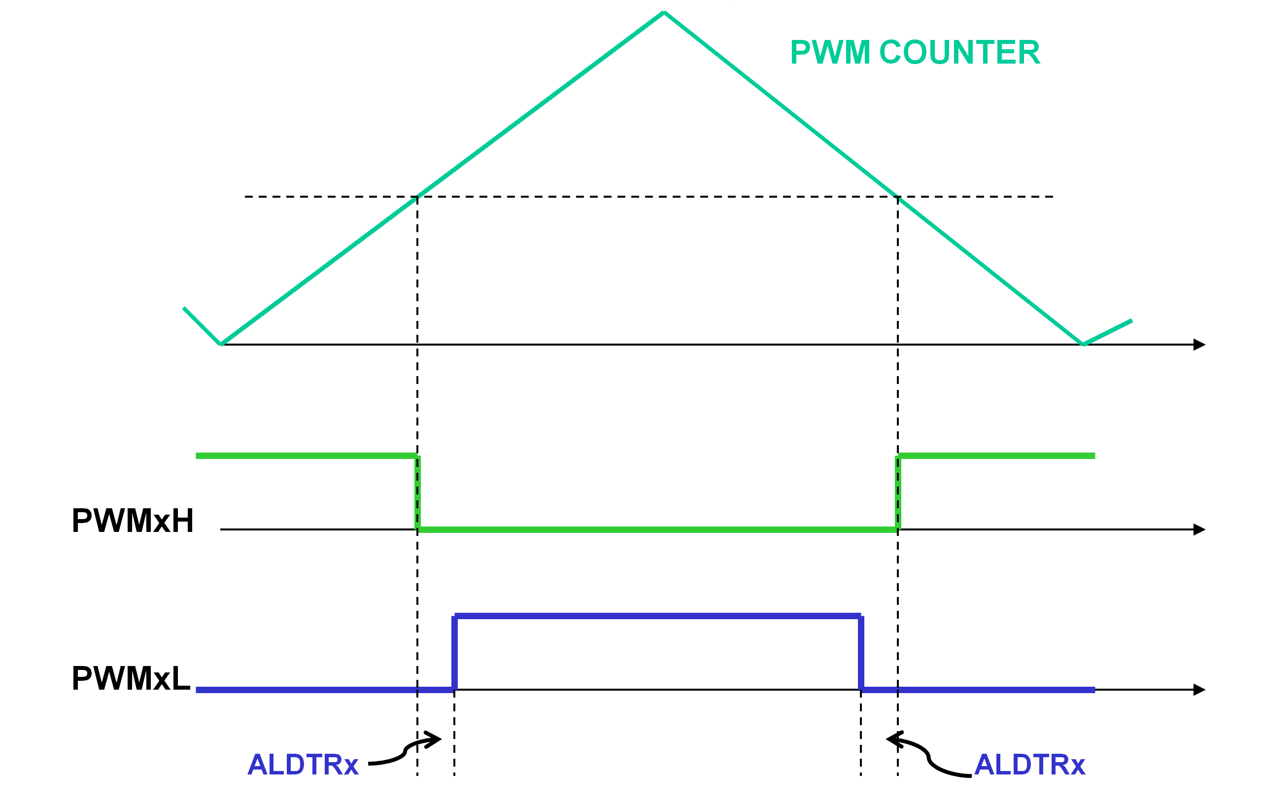
casainho, can you please check my recent thougts regarding the PWM scheme.

file.php


the high-side mosfet is active in the marked period, and the low-side mosfet is switched complementary minus dead-time, like shown in this picture

center-aligned-pwm.png


I want to understand why my motor ran without problems with the higher PWM frequency, even though the table values were too high....

regards
stancecoke
 
stancecoke said:
I want to understand why my motor ran without problems with the higher PWM frequency, even though the table values were too high....

After playing around in Excel a little, I can give me the answer myself :)
As long as ui8_duty_cycle is not bigger than 129, we won't get capture/compare register - values bigger than 192.
And as I ran the motor without load, no high ui8_duty_cycle-values were needed to get the motor to top speed :idea:

regards
stancecoke
 
duty_cycle = (duty_cycle >> 1) + (duty_cycle >> 2);

Is equal to = duty_cycle * 0.75 ; pwm freq * 1.33

So maybe with that sum and 2 right shift operations, we can scale down in real time the table values. You would just need to change the TIMER1 configuration and the values that are readed from the table, as also the middle value. I think everything else would be the same.
 
I think it's better to spend another array that is scaled once at startup from the original table. (if we have sufficient memory space left) Or solve it with a #ifdef.
And we have to rescale all the user relevant data that need a reference to real seconds/minutes/hours (only max cadence and wheelspeed/wheelspeedlimit as a first guess)
So it would be fine to calculate all necessary constants from the PWM-frequency. That's some work for one time, but later this will make changes much faster :)

regards
stancecoke
 
geofft said:
honya96 said:
geofft said:
Battery option 12s (a popular choice nowadays) so the LCD3 battery monitor gives meaningful info. I guess however that the current options are maybe fixed by the display firmware and can't be changed...?
Correct, its set by display itself (P5) I think. But still if it affects something, we need also 14s 20s and 16s (in this order) to cover the most.

I found using 12s (with the stock controller firmware) that there was no P5 selection that gives a useable battery monitor, I guess that goes for other 'non standard' battery types too. Ideally you would be able to input any battery configuration (that's safe for the controller) and the battery monitor, etc, would be scaled accordingly. Maybe a future project for somebody...... :roll:

My original assumtion was that p5 has nothing to do with controller (firmware) but now I realize that it has to, because if you desolder lvc resistor, it shows empty. So A better meter can probably be implemented in firmware for each battery configuration. Reading no load voltage second after releasing throttle/pas/regen (simple but working) and then 1bar means 3.4v 2 bars mean 3.8v etc( for example ) multiplied by number of cells will give pretty acurate reading refreshed everytime you are rolling free.
 
stancecoke said:
I think it's better to spend another array that is scaled once at startup from the original table. (if we have sufficient memory space left) Or solve it with a #ifdef.
And we have to rescale all the user relevant data that need a reference to real seconds/minutes/hours (only max cadence and wheelspeed/wheelspeedlimit as a first guess)
So it would be fine to calculate all necessary constants from the PWM-frequency. That's some work for one time, but later this will make changes much faster :)
Seems a good idea.

honya96 said:
Reading no load voltage second after releasing throttle/pas/regen (simple but working) and then 1bar means 3.4v 2 bars mean 3.8v etc( for example ) multiplied by number of cells will give pretty acurate reading refreshed everytime you are rolling free.
Current firmware implementation:
Code:
  // calc battery pack state of charge (SOC)
  ui16_battery_volts = motor_get_ADC_battery_voltage_filtered () * ADC_BATTERY_VOLTAGE_K;
  if (ui16_battery_volts > BATTERY_PACK_VOLTS_100) { ui16_battery_soc = 16; } // 4 bars | full
  else if (ui16_battery_volts > BATTERY_PACK_VOLTS_80) { ui16_battery_soc = 12; } // 3 bars
  else if (ui16_battery_volts > BATTERY_PACK_VOLTS_40) { ui16_battery_soc = 8; } // 2 bars
  else if (ui16_battery_volts > BATTERY_PACK_VOLTS_20) { ui16_battery_soc = 4; } // 1 bar
  else { ui16_battery_soc = 3; } // empty
  
  ...
  
    // preparing the package
  // B0: start package (?)
  ui8_tx_buffer [0] = 65;
  // B1: battery level
  ui8_tx_buffer [1] = ui16_battery_soc;

Code:
// *************************************************************************** //
// BATTERY

// ADC Battery voltage
// 29.8V --> 110 (8bits ADC)
// 22.1V --> 81 (8bits ADC)
// 1 ADC step 8 bits --> 0.287 volts
#define ADC_BATTERY_VOLTAGE_K 73 // 0.272 << 8

#if BATTERY_LI_ION_CELLS_NUMBER == 7
#define COMMUNICATIONS_BATTERY_VOLTAGE 24
#define ADC_BATTERY_VOLTAGE_MAX 108 // 29.4V (7S * 4.2V)
#define ADC_BATTERY_VOLTAGE_MED 5632 // 24V: 88 << 6
#define ADC_BATTERY_VOLTAGE_MIN 77 // 29.4V <(7S * 3.0V)
#elif BATTERY_LI_ION_CELLS_NUMBER == 10
#define COMMUNICATIONS_BATTERY_VOLTAGE 36
#define ADC_BATTERY_VOLTAGE_MAX 162
#define ADC_BATTERY_VOLTAGE_MED 8448
#define ADC_BATTERY_VOLTAGE_MIN 115
#elif BATTERY_LI_ION_CELLS_NUMBER == 13
#define COMMUNICATIONS_BATTERY_VOLTAGE 48
#define ADC_BATTERY_VOLTAGE_MAX 216
#define ADC_BATTERY_VOLTAGE_MED 11264
#define ADC_BATTERY_VOLTAGE_MIN 154
#endif

//#define BATTERY_OVER_VOLTAGE_PROTECTION

// Considering the follow voltage values for each li-ion battery cell
// State of charge 		| voltage
#define LI_ION_CELL_VOLTS_MAX 	4.2
#define LI_ION_CELL_VOLTS_100 	4.05
#define LI_ION_CELL_VOLTS_80 	3.93
#define LI_ION_CELL_VOLTS_60 	3.78
#define LI_ION_CELL_VOLTS_40 	3.60
#define LI_ION_CELL_VOLTS_20 	3.38
#define LI_ION_CELL_VOLTS_0 	3.20
#define LI_ION_CELL_VOLTS_MIN 	3.0

#define BATTERY_PACK_VOLTS_100	(LI_ION_CELL_VOLTS_100 * BATTERY_LI_ION_CELLS_NUMBER) * 256
#define BATTERY_PACK_VOLTS_80 	(LI_ION_CELL_VOLTS_80 * BATTERY_LI_ION_CELLS_NUMBER) * 256
#define BATTERY_PACK_VOLTS_60	(LI_ION_CELL_VOLTS_60 * BATTERY_LI_ION_CELLS_NUMBER) * 256
#define BATTERY_PACK_VOLTS_40	(LI_ION_CELL_VOLTS_40 * BATTERY_LI_ION_CELLS_NUMBER) * 256
#define BATTERY_PACK_VOLTS_20	(LI_ION_CELL_VOLTS_20 * BATTERY_LI_ION_CELLS_NUMBER) * 256
#define BATTERY_PACK_VOLTS_0	(LI_ION_CELL_VOLTS_0 * BATTERY_LI_ION_CELLS_NUMBER) * 256

Code:
void do_battery_voltage_protection (void)
{
  // low pass filter the voltage readed value, to avoid possible fast spikes/noise
  ui16_adc_battery_voltage_accumulated -= ui16_adc_battery_voltage_accumulated >> 6;
  ui16_adc_battery_voltage_accumulated += ((uint16_t) ui8_adc_read_battery_voltage ());
  ui8_adc_battery_voltage_filtered = ui16_adc_battery_voltage_accumulated >> 6;

  if (ui8_adc_battery_voltage_filtered > ADC_BATTERY_VOLTAGE_MAX)
  {
#ifdef BATTERY_OVER_VOLTAGE_PROTECTION
    // motor will stop and battery symbol on LCD will be empty and flashing | same as low level error
    motor_controller_set_state (MOTOR_CONTROLLER_STATE_UNDER_VOLTAGE);
    motor_disable_PWM ();
    motor_controller_set_error (MOTOR_CONTROLLER_ERROR_91_BATTERY_UNDER_VOLTAGE);
#endif
  }
  else if (ui8_adc_battery_voltage_filtered < ADC_BATTERY_VOLTAGE_MIN)
  {
    // motor will stop and battery symbol on LCD will be empty and flashing
    motor_controller_set_state (MOTOR_CONTROLLER_STATE_UNDER_VOLTAGE);
    motor_disable_PWM ();
    motor_controller_set_error (MOTOR_CONTROLLER_ERROR_91_BATTERY_UNDER_VOLTAGE);
  }
}
 
Finally some success in the garage today. Firstly the reverse pedalling problem:-

casainho said:
You can adjust on main.h:
Code:
#define PAS_ABSOLUTE_MIN_CADENCE_PWM_CYCLE_TICKS  (156250 / PAS_NUMBER_MAGNETS) // min hard limit to 6RPM PAS cadence
You will need to lower the value of 156250, that as you can see is for 6 RPM. Can it work ok with minimum 10 RPM? 15 RPM?

...because of the extremely variable and inconsistent nature of this problem it was difficult to get a reliable conclusion to this, but eventually I can tell you this much:-

The display now confirms that pas assist is definitely being triggered by reverse pedalling.

A value (in the line shown above) down to around 60,000 'ticks' seems to remove the issue. This equates to around 15rpm so not sure how well that will work on the road, maybe will test tomorrow. I wouldn't make any changes based on this information, as I said before, I'm extremely suspicious about the quality of the signal my pas sensor is producing, should have a replacement soon.

Display comms problem:-

The key is the ui8_crc ^ x, where values of 10, 9 and 2 works. If you send me your LCD3, I can try different values up to get it working but maybe would be more efficient if you could try by yourself -- you would need to changes, let's say that ui8_crc ^ 10 starting like from 0 up to 8 (2 is already on the firmware, no need to test). Maybe you will find it is value 3 that works for your LCD and then I would add that value to the firmware.

....success with this, I found a 'key' value of 5 works for my controller (KT36/48SVPR, from PSWpower), so assist levels and speed controls are now all working correctly. Is there any reason you can't just enable all the keys?

- find the correct value for FOC_READ_ID_CURRENT_ANGLE_ADJUST to your motor, as it seems to ask a lot of current and the controller seems to get to much hot

.....didn't get a chance to play with today, hopefully will get time tomorrow.
 
My 7 years old son can't yet understand, but I am sure he will be proud of is dad! -- really happy to work, professionally, for a greener environment <3

I joined BFO Mobility, a German company that develops high technology for electric bicycles, like ABS brakes!! They also develop products for electrified micromobility as the Flynn scooter: http://www.go-flynn.com/index_en.php

[youtube]bCsUi-Q73rg[/youtube]
 
geofft said:
A value (in the line shown above) down to around 60,000 'ticks' seems to remove the issue. This equates to around 15rpm so not sure how well that will work on the road, maybe will test tomorrow. I wouldn't make any changes because of this information, as I said before, I'm extremely suspicious about the quality of the signal my pas sensor is producing, should have a replacement soon.
Waiting for your test.

geofft said:
....success with this, I found a 'key' value of 5 works for my controller (KT36/48SVPR, from PSWpower), so assist levels and speed controls are now all working correctly. Is there any reason you can't just enable all the keys?
Just added to firmware.
That "key" is like a result of an algorithm that verifies all the data and search for possible errors (due to noise on electronics, etc). If we put all the keys, it may be like if we disable the algorithm... or at least reduce the effectiveness of detecting the errors.
 
casainho said:
I joined BFO Mobility, a German company that develops high technology for electric bicycles,

Good luck! It seems you're one of those rare people who has found a job they actually enjoy doing.... :D
 
honya96 said:
So A better meter can probably be implemented in firmware for each battery configuration. Reading no load voltage second after releasing throttle/pas/regen (simple but working) and then 1bar means 3.4v 2 bars mean 3.8v etc( for example ) multiplied by number of cells will give pretty acurate reading refreshed everytime you are rolling free.

This sounds like an excellent plan. If it could be done solely within the controller firmware for any (safe) battery configuration that would make a great additional feature.
 
geofft said:
This sounds like an excellent plan. If it could be done solely within the controller firmware for any (safe) battery configuration that would make a great additional feature.

As I "understand" Casainho's answer, it is allready implemented some way.. I wish I was a programmer to be able to work on these things. :cry:
There is sooo much to add still, after it will be working atleast as original and easily flashable.
 
Yes, different batterie packs voltage can be custom and is mostly implemented - not all options, but they can be added as needed. If someone need a specific value other than current 7, 10 and 13S, please ask. But please ask only what you need and will use, because you will have to test and give feedback :)
 
casainho said:
If someone need a specific value other than current 7, 10 and 13S, please ask. But please ask only what you need and will use, because you will have to test and give feedback :)

Ok, I'll start the ball rolling....12s please :D

P.S. I'm in no rush for this, please attend to only when you have sufficient time.
 
honya96 said:
I wish I was a programmer to be able to work on these things. :cry:

...yep, me too, I'm working at the extreme edge of my abilities here :shock:

You obviously have a good grasp on how these things work, why not have a go, get a spare controller and try flashing this firmware? It's not as daunting as it first appears and, as you can see, these guys give fantastic help if you run into problems.
 
stancecoke said:
I think it's better to spend another array that is scaled once at startup from the original table. (if we have sufficient memory space left)
We can solve this much easier without additional need of memory. We can just run a for-loop that does the scaling once at startup on the original array...
Code:
for(a = 0; a < 256;a++) {// array scaling to PWM frequency
    ui8_svm_table [a]=ui8_svm_table [a]*16000000/PWM_CYCLES_SECOND/4/256;
}
Of course we have to cast the values to ui16 temporaribly.

regards
stancecoke
 
stancecoke said:
We can solve this much easier without additional need of memory. We can just run a for-loop that does the scaling once at startup on the original array...
Code:
for(a = 0; a < 256;a++) {// array scaling to PWM frequency
    ui8_svm_table [a]=ui8_svm_table [a]*16000000/PWM_CYCLES_SECOND/4/256;
}
Of course we have to cast the values to ui16 temporaribly.
Although it will work, I would prefer to go with another table and ifdef. I can see as advantages:
- less memory used (yes, it may be few anyway)
- easy to visual inspect the values on the table and spot any error
 
This is the diff of changes I did on main.h (where user should not change). On config.h, user selects the BATTERY_LI_ION_CELLS_NUMBER, like BATTERY_LI_ION_CELLS_NUMBER = 7.

Next thing that need to be updated is the configuration tool. Let's see if I can do it soon.


And the final code (no tested but it is on master branch as I am confident about it):
Code:
// *************************************************************************** //
// BATTERY

// ADC Battery voltage
// 29.8V --> 110 (8bits ADC)
// 22.1V --> 81 (8bits ADC)
// 1 ADC step 8 bits --> 0.287 volts
#define ADC_BATTERY_VOLTAGE_PER_ADC_STEP 0.272 // this value was found experimentaly, to beter represent the real value
#define ADC_BATTERY_VOLTAGE_K 73 // 0.272 << 8

#define COMMUNICATIONS_BATTERY_VOLTAGE	((uint8_t) (BATTERY_LI_ION_CELLS_NUMBER * 3.45)) // example: 7S battery, should be = 24
#define ADC_BATTERY_VOLTAGE_MAX 	((uint8_t) ((BATTERY_LI_ION_CELLS_NUMBER * LI_ION_CELL_VOLTS_MAX) / ADC_BATTERY_VOLTAGE_PER_ADC_STEP))
#define ADC_BATTERY_VOLTAGE_MED 	((uint8_t) (COMMUNICATIONS_BATTERY_VOLTAGE / ADC_BATTERY_VOLTAGE_PER_ADC_STEP))
#define ADC_BATTERY_VOLTAGE_MIN 	((uint8_t) ((BATTERY_LI_ION_CELLS_NUMBER * LI_ION_CELL_VOLTS_MIN) / ADC_BATTERY_VOLTAGE_PER_ADC_STEP))

// Considering the follow voltage values for each li-ion battery cell
// State of charge 		| voltage
#define LI_ION_CELL_VOLTS_MAX 	4.2
#define LI_ION_CELL_VOLTS_100 	4.05
#define LI_ION_CELL_VOLTS_80 	3.93
#define LI_ION_CELL_VOLTS_60 	3.78
#define LI_ION_CELL_VOLTS_40 	3.60
#define LI_ION_CELL_VOLTS_20 	3.38
#define LI_ION_CELL_VOLTS_0 	3.20
#define LI_ION_CELL_VOLTS_MIN 	3.0

#define BATTERY_PACK_VOLTS_100	(LI_ION_CELL_VOLTS_100 * BATTERY_LI_ION_CELLS_NUMBER) * 256
#define BATTERY_PACK_VOLTS_80 	(LI_ION_CELL_VOLTS_80 * BATTERY_LI_ION_CELLS_NUMBER) * 256
#define BATTERY_PACK_VOLTS_60	(LI_ION_CELL_VOLTS_60 * BATTERY_LI_ION_CELLS_NUMBER) * 256
#define BATTERY_PACK_VOLTS_40	(LI_ION_CELL_VOLTS_40 * BATTERY_LI_ION_CELLS_NUMBER) * 256
#define BATTERY_PACK_VOLTS_20	(LI_ION_CELL_VOLTS_20 * BATTERY_LI_ION_CELLS_NUMBER) * 256
#define BATTERY_PACK_VOLTS_0	(LI_ION_CELL_VOLTS_0 * BATTERY_LI_ION_CELLS_NUMBER) * 256
// *************************************************************************** //
 
Back
Top