KT LCD3 firmware -- Flexible OpenSource firmware for Kunteng KT-LCD3

Kiso79 said:
Hi there guys,

Thanks for all the great work done so far!
I saw that there was a question last year on having multiple profiles on a setup. Is this something that had any progress?

On another note. Has there been any work on the lcd08? I know it's a different beast, but it is a pretty cool evolution on the display.

Thanks in advance.

Kim
We moved to most powerful LCDs like Bafang 850 color LCD and SW102 Bluetooth, as KT-LCD3 is now memory full and so there is no future path for it.
 
Sztef89 said:
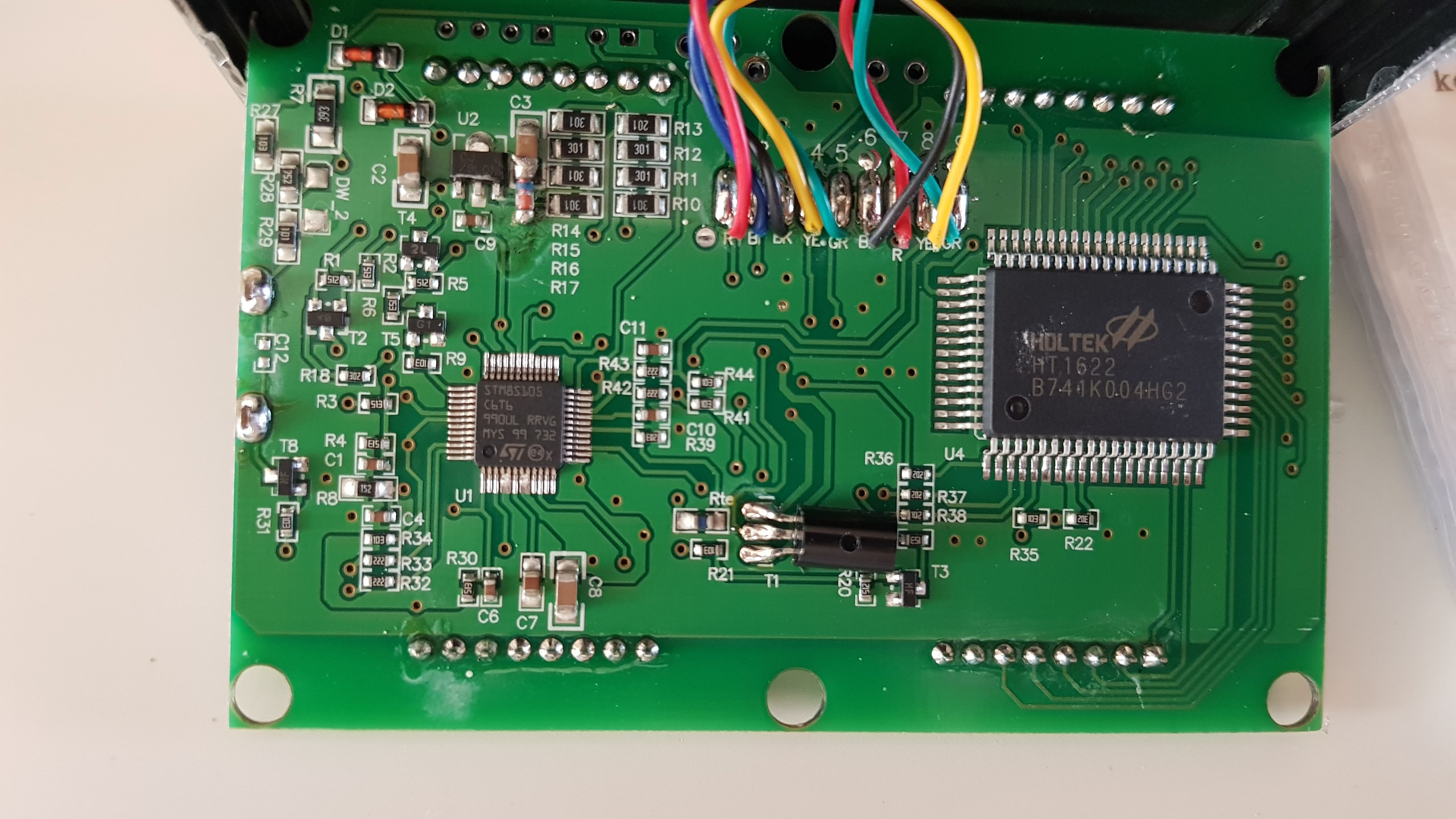
60Volt version looks like that inside :wink:

Vu7byNS.jpg

Hi :)
Where the atmospheric air temperature sensor is located ?
 
Hello, as I moved to a new color display. Is there a way to bring LCD kt3 to stock firmware, so it can work with kt controllers? Anyone have the stock files?
Thanks
 
Hi there,

This thread was worth creating an account. Love your work and I would like your opinion on data logging the communication.
Replacing the original FW with an open-source one is difficult without knowing how the attributes and parameters are implemented.

I am trying to say, that I do not expect I can replace my KT-LCD3.
I was thinking of putting a daughter board to data log. Like an open-source ebike data logger - a read-only controller :)
The communication seems serial in nature between LCD and motor controller.

What do you think? Is it something to consider?
Or is it better to just hack the controller itself.
 
Hello,
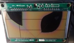
i've broke my LCD3 screen but device still work - i can switch assistance, turn on-off etc.
IMG_20220825_114553.jpg
(here is more detailed disassembly of KT-LCD3 with PCB photos - https://electrotransport.ru/ussr/index.php?topic=58478.msg2217894#msg2217894)

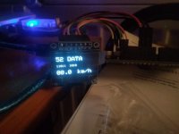
I've tried to connect arduino board with oled screen to get feedback about speed at least, so far results are so-so - for oled need a lot more power then for LCD used in the device, and i've unstable uart readings through my arduino - dunno what is it - my programming skills or defected board...
1e42z9z.jpeg

I've a question about flashing this device - in very first video it is seen cable, connected to the pcb:
Connector1.jpg
Obviously this is SWIM-cable for debugging STM-based devices. Could someone explain - do i need to purchase separate device to connect to STM this way or is there a way of connecting directly to PC with this port? Maybe i can connect to arduino and read signals which STM sending to screen (to chip HT1622) and make analogue of LCD panel, but with other screen (graphical), connected to arduino? Or this was bad idea from the beginning?
 
Back
Top