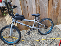
Ebmx melting throttle button

skuzzlebut

1 mW
Joined
May 7, 2025
Messages
15
Location
Canada
Just made a sick electric bmx. 12v 250w gear reduction chain drive motor, running on 20v drill batterys. More than enough for some added fun at the skatepark at gets me about 20-30kmph on flat ground. Throttle applied while pedaling makes short work of hills. I'm trying to run it without a controller to save on space and cost. I keep melting the intermittent buttons I'm using as throttle, they are all I need but need something more hd for when i run the motor for long periods uphill. Variable speed would be nice if possible on a intermitent button. I'm using a 12/24v 20amp heavy duty button from Amazon. I saw they do make a 50 amp but the issue with the last 20amp one was the plastic housing around the contacts melted to the point they separated internally and I doubt a 50 amp button would fix that issue. Any advice?
 

Attachments

  • bmx.png
    bmx.png
    6.6 MB · Views: 8
I had 2 pwm controllers and they melted even though they were rated 72v or so, however they were cheap. they just have a knob to adjust the power and a button to controll so hard to work both at once. I am liking the turbo button as well lol only problem is the wheel shifting (chain loosens) at stop or low speed and a lot of strain on the system.
Without details on the ones that failed I couldn't say for sure why, but:

Generally it sounds like they weren't meant to operate motors (inductive loads can be different from resistive ones, and require different designs; also brushed motors make craploads of RF at the brushes that can blow up FETs), and/or were not meant for the amount of current you are drawing (which as previously noted could be as high as a hundred amps or more at startup and under higher loads).

I've seen numerous ones on ebay, amazon, etc with an on/off switch and a separate pot to control speed that are not meant for use on ebikes, etc., most with open-cage covers, that would require active fan cooling to do anything close to their claimed ratings for more than a few seconds, if even that. Most are rated for low current, 5-10A, sometiems claiming a "max" of two or three times that, but that's a few seconds burst at most.

Most of these things are really cheaply designed and built, and don't really have much heat dissipation or a good current-limiiting design, so when excessive loads occur and they should be rolling back PWM duty cycle, they don't, or don't do so fast enough, and the FETs heat up so fast they just pop. If they had better heatsinking and active cooling, they might survive long enough to get past that anyway, but even that won't save one that cant' actually do proper current limiting. There's even plenty of really cheap brushed scooter / ebike motor controllers that have this problem, including some of the YKK brand ones discussed here and there on ES.

But it's all just speculation without specifics on what the failed units were, and exactly how they were used.
 
Well, a relay is just a remote controlled switch, so it is just on and off. If you are using a resistive (potentiometer) throttle, it could be wired to activate the relay when it is rotated far enough, essentially all the way on, but it wouldn't give you any variable control.
The coils on a mechanical relay can draw 100mA or more. I don't think a hall based throttle can provide that, since it's really only designed to provide a voltage signal to the controller.
 
The coils on a mechanical relay can draw 100mA or more. I don't think a hall based throttle can provide that, since it's really only designed to provide a voltage signal to the controller.
That's why I stated "If you are using a resistive (potentiometer) throttle". ;)

The typical hall based throttle (ss49e or clone thereof) coudln't operate at the votlages needed for the typical relay as discussed in this thread; usually theyre around 6v, maybe 8v absolute max supply voltage. There are 5v-coil relays, and there are hall sensor that could be used that can handle those voltages.

But as you note, it's unlikely any of them are able to source or sink as much current as the average relay coil for the size relays needed here would use. Some tiny relays use very tiny coil currents, and could possibly be used this way if a diode was also used across the coil to prevent damage to the hall from flyback current as the coil turns off...but it would still only be a switch, not a variable control. ;)
It's probably better to fry a throttle than it is to burn out the 5V regulator in the controller. Just a bad idea no matter how you look at it.
 
It's probably better to fry a throttle than it is to burn out the 5V regulator in the controller. Just a bad idea no matter how you look at it.
I don't really understand what you mean, since we were talking about using a throttle to switch a relay coil on/off, not even using a controller?
 
Could use a limit switch. Micro one would fit in a throttle housing,

That's if you really have a thing for vroom vroom style throttles. Otherwise, there's neater options.

Still good to use a limit switch in some way though I reckon, because to my ear they're the best sounding of all switch types, very satisfying click they make, similar to relays.

Momentary push buttons with coil springs are awful, make no sound at all.
 
Ok got it relays are on off no variable controll.
If you use a solid state relay you might be able to drive it with a Hall effect throttle. Most linear hall sensors can take 18 volts.
But would still only be on or off, no variable action? Most generic throttles have this setup?
Could use a limit switch. Micro one would fit in a throttle housing,

That's if you really have a thing for vroom vroom style throttles. Otherwise, there's neater options.

Still good to use a limit switch in some way though I reckon, because to my ear they're the best sounding of all switch types, very satisfying click they make, similar to relays.

Momentary push buttons with coil springs are awful, make no sound at all.
You mean using a limit switch style button instead of the one I'm using now?
I'm sure you could fit one in a throttle housing and rig it to activate but I'd rather not and doubt I could haha. But are you saying a limit switch can be used with variable controll?

 
Nah, sorry, no single switch can provide variable control. (You need rheostat for that, like Amberwolf described.) I meant used in conjunction with a relay.

Limit switch can be used same as a push button. They have a lever that pushes the button for you. And instead of a coil spring, there's something else, presumably a flat spring, that gives a quick flick. For momentary switches, much nicer - you get tactile and audible feedback, unlike the mushy feeling of a coil spring where you don't even know if/when it's activated.
 
Ok got it relays are on off no variable controll.

But would still only be on or off, no variable action? Most generic throttles have this setup?

No. A throttle is just an input device to give you variable control over a motor controller. If you don't have a motor controller, there's not really a point to using a throttle.


I'm sure you could fit one in a throttle housing and rig it to activate but I'd rather not and doubt I could haha. But are you saying a limit switch can be used with variable controll?
Unless you use a controller such as been previously linked, or a giant rheostat, etc., you won't have variable control.

You can build a relay-controller like old forklifts used, but you have to take your batteries apart to the cell level to get that to work, with the various issues as previously described.
 
If you use a solid state relay you might be able to drive it with a Hall effect throttle. Most linear hall sensors can take 18 volts.
The SS49E (what I've seen in a couple of throttles) are rated 8v absolute max (6.5v typical max supply), according to the datasheet at the Mouser page here, though the page itself says they can do 10v, so I don't know what their actual rating is. :/ https://www.mouser.com/ProductDetail/Honeywell/SS49E?qs=/fq2y7sSKcJBD3o5K2Vcgg==

I was going to try to link to some that can take higher voltage, but the mouser page https://www.mouser.com/c/sensors/magnetic-sensors/board-mount-hall-effect-magnetic-sensors/ doesn't have any parameter for supply voltage higher than 5.5v, which doesn't make sense if they think the 49E can do 10v.... :?

Weird.
 
OK, I stand corrected. The SS41s can take more.
So you'd need a 5v supply to use a throttle, which would be more complicated.
My old Zappy scooter used a trigger switch to activate the relay. Those are probably available somewhere.
 
OK, I stand corrected. The SS41s can take more.
Yeah, the digital halls usually take 20-30V depending on model, brand, and version, some can take higher voltage on the open-collector signal output than they do on the supply voltage (though in the average ebike they don't get used that way).


So you'd need a 5v supply to use a throttle, which would be more complicated.
If using the throttle to control a relay controller stack (for step-variable control like old forklifts), instead of just as a "switch" (which it wouldn't be good at anyway), where the battery has to be opened up to access all the cells individually anyway, the most negative cell in the pack could be used to power the throttle for some of the sensors that can operate.

But it's kinda pointless to be using a variable-output throttle to do any of this kind of control, since you can't actually use it's variablility for a simple switch usage. ;)


My old Zappy scooter used a trigger switch to activate the relay. Those are probably available somewhere.
There are a bunch of different kinds here:
though none of them are "trigger style". (pretty sure there are a number of them made, just not listed there).

An ebrake lever could be used for that easily enough, however I wouldn't because it would be training the wrong reactions to a brake lever, and/or forcing overcoming learned reactions, to use a brake lever for a throttle. Could potentially cause a reaction delay or wrong reaction at some point trying to do an emergency stop. :(

A DIY trigger switch could be made from an old drill or other trigger-controlled on/off powertool, and either a 3D printed housing or modifying any kind of clamp (including reflector mounts) to hold it to the handlebars. Could even use an entire reflector and mount and silicone the trigger to the reflector itself, in whatever position makes it useful to the rider.
 
Most automotive "12V" relays can easily operate at 15v for coil voltage, and they might handle the 20V battery voltage alright. They make them in at least 30A types (I use some of that size in SB Cruiser to switch lighting, etc).

The ones I use have fuseholders in them with blade fuses preinstalled, so if they see a current higher than they can hanlde the fuse blows, protecting the wiring and the relay and the devices
Would the fuses in my case not have to be massive?
Any reason this relay and button wouldn't work?
And another question. If I were to try this same setup with a 24v motor (same battery) I would have reduced motor rpm and power?
Theres a more readily available/ cheaper 24v 250w version looks like it's identical to my 12v 250w motor. Does the voltage actually matter and is it possible they are the exact same motor?

2Pcs Motorcycle Handlebar Switch​


iRhapsody 250A 12V Relay, 4 Pin SPST High Current Control, Split Charge Switch​

 
Last edited:
Would the fuses in my case not have to be massive?
How much current does your system use, worst case load, at peak?

The fuse and all components in series with the battery to motor connnections must be able to handle that.

If you haven't measured the current (wattmeter, clamp-on ammeter, etc) then you won't know what parts to use until you replace them with bigger and bigger ones until they stop breaking when you're using them. ;)
 
And another question. If I were to try this same setup with a 24v motor (same battery) I would have reduced motor rpm and power?
Theres a more readily available/ cheaper 24v 250w version looks like it's identical to my 12v 250w motor. Does the voltage actually matter and is it possible they are the exact same motor?

Usually hte motors are rated for a particular speed at a particular voltage, which tells you the kV or RPM/volt, which you can use to tell how fast it will spin given a particular voltage.

They *may* be identical to other voltage rating versions of the same motor, other than the kV, or they may be bulit differently such as with higher resistance windings so current draw is lower, etc.

Generally it's tough to tell just by looking at the motor whether two apparently identical motors really are, without testing them for their various characteristics vs each other with the same test setup.

Best guess is that the 24v version, if rated for the same RPM, will spin at half the RPM the 12v version does for the same voltage input, having half the kV.

If there is no rated speed at a rated voltage, you can only guess what it will actually do until you test it.
 
Any reason this relay and button wouldn't work?

iRhapsody 250A 12V Relay, 4 Pin SPST High Current Control, Split Charge Switch​

1747362559448.png
Well, it looks hefty, though the recommendation to use less than the max rating means that it isn't *really* able to handle the full rating (because it should be rated for what it could handle all day forever, unless it specifies a time and duty cycle, which it doesn't).

So consider it to really be capable of less than what it recommends, which is "try to stay 10 to 15% below what the rate is for" so less than 0.85 x 250A = 212A...how much less? Who knows....

Suprisingly they actually give the pickup (turn on) and dropout (turn off) votlages the coil requires to operate the relay, and the coil current and resistance, which is almost never provided for amazon/ebay/ali* etc parts. Those might be accurate, might not, given the other rating stuff above, but they probably are at least close.

Whether that relay would work or not; I can't say since I don't know how much current your system actually draws. Maybe? Probably? Worth a shot?

Probably the coil could handle the overvoltage you'll be giving it; you'll just have to check if it gets hot or not. To test that, just wire the coil itself to your switch and battery, don['t wire up the contacts yet. Turn the relay on and wait a few minutes. If the relay is hot, the coil is getting hot and heating it up. Whether that's a problem depends on how hot and whether there's airflow around the relay or if it's in a box or bag, etc. if it starts smoking, well, that's a fair sign of bad things happening. ;)


The switch could switch the coil current easily enough, if that's what you want to use it for, to turn the relay on and off. How good the switch is? Dunno, never used that kind.
 
Ok cool I'll try the relay, worth a shot at the price. I'm sure 200+ amps will be plenty. I have the wattmeter you suggested on the way. I'd love to have that info, its just taking it's time arriving from the states.
Im going to order a 24v kit and do some testing, it does just seem like double the rpm of the 12v and completly identical from the outside. I can always return if it doesn't suit my purpose or make another project with 36v batterys. So helpful you guys 🙏 sorry for the million questions I've learnt a lot!
 
If you use too high a coil voltage type of relay, it could drop out (turn off) whenever the battery voltage drops under load. That can actually be used as a feature,
I like the sound of this as a type of bms. Sounds like a lot of trial and error but I'd like to try to implement this after I figure out how to and do some testing!
 
Back
Top