• Hello ES! We could use some help to get us past the finish line on building the new knowledgebase for the forum.
    Can you donate? Please see our fundraising page. Thank you!

Emulator for Torquesensors Bafang CAN + UART, ERider ....

stancecoke

Minor legend
Joined
Aug 2, 2017
Messages
3,492
Location
Bavaria, Germany
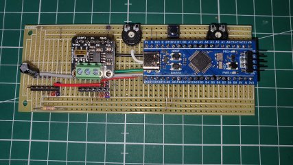
As it is quite tricky to activate a torquesensor on a workbench (turning the BB shaft and put on a torque at the same time :)), I've build an emulator, that generates the needed signals. Cadence and torque can be set by two pots, a button on the PCB starts and stops the signal generation. If stopped, the idle signal is send permanently. I gave a small sneak preview on the Bafang CAN controller OSF firmware thread, now the universal model for the CAN and the analogue sensor versions is working. It's a little soldering, but really easy to build. Maybe it is worth to design an own PCB and let it build by JLCPCB or other PCB manufacturers.
If there is interest, I can provide a precompiled hex file for the Bluepill in a release.


overview_photo.JPG


The emulator generates the CAN message every 400ms in the format that is described at github. I have no controller for a CAN sensor, so I can't test it.

1763061809554.png


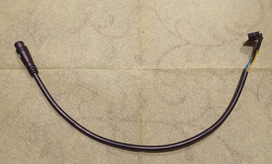
The most expensive parts are the Higo connectors for the CAN and the UART connectors. The device works stand alone, just plug it to the torquesensor connector of your processor. No laptop, smartphone or anything else is needed :cool:
1763062566242.png
 
Last edited:
how the wiring should be made
I've drawn a schematic in "Fritzing" and added the Fritzing file to the documentation folder of the repo.
You can find a pdf with better resolution there also, as a screenshot is not readable in detail.
I'm using an SN65HVD230 CAN transceiver board, that is not in the Fritzing library, any other will work also and will have the same pins...

The precompiled hex-file can be found in the release v0.1:


1763138869506.png


schematic.JPG
 
Last edited:
Ok thanks!
I looked at my boards and they are visual little different, no jumpers but 3 buttons and it's labeled WeAct with STM32F103CBT6 but i guess it should work too without changes.
 
Yes, should work anyway. But I had to publish an update, as the code ended in an error handler, when no CAN device was connected, so reload the hexfile, the link is still valid.
 
Just finished it. Although i have no led activity, the output torque on the analog part is 900mV. After a press on the button i can vary the torque on the analog output to around 3.3V
With the other poti and with my multimeter set to frequency i can vary the frequency on the other output pins. Duty cycle stayed at around 50% if that is correct?
Will check more in depth and the canbus tomorrow. Not sure why the led does not flash, maybe because it's slightly different board who knows.
Edit: With the picture full size i see the text next to the led, it's on PB2 if that is an indication to what port it is connected, so that's probably why led is not working. I will put a led on PC13.

Emulator TorqueSensor bafang.jpg
 
Last edited:
I will put a led on PC13.
I've just published a new release with PC13 and PB2 as LEDs, so it should work on both Bluepill boards now. ;)
Further I've added a Jumper to PA4, that let you disable the torquesignal output, to emulate simple PAS also. If you connect PA4 to GND, the torque output is disabled.


I'm looking forward to see, if the CAN connector works also!
 
Last edited:
Super! In further test I connected laptop with a can device to it and the can signal for torque and cadence is working. Torque from 700mV to 3255mV and cadence from 33 to 120. When pressing button to stop, the can torque go's to 700mV so i guess it works like it should. Still need to prepare a cable with that square / trapezium canbus connector so i finally can test on hub controller. But first i need to reprogram so the onboard led can work too for a Bluepill STM32F103CBT6
 
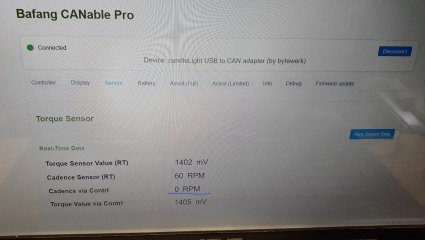
Decided to try it first before adding the extra jumper to disable torque. So i connected it up to controller with front motor. I can see the torque data and cadence from the torque emulator in the controller data stream. Also Canable Pro shows the RT torque and cadence from emulator. It shows also torque value via controller but not the cadence via controller.
It looks like controller does not process? the cadence coming from emulator?

The controller does have a torque table but looking at controller params setting it shows: Cadence sensor signals/ rotation:16
Motor trigger type: Cadence sensor + Throttle
If i select other option; Torque sensor + Throttle it accept it but no dice.
---------------------------------------------------------------------
Just for information: I looked at recorded data from M400 which has torque sensor with can signals. That "progressive byte" from torque sensor is running (counting) like hell lol. I had to put playback in super slow motion to see, (normal is every 10 milliseconds?) Progressive byte counts from 00 to FF and then start all over again and again. Maybe it matters and needs to count for the controller somehow but i really don't know.

I'm going to add the jumper to the emulator so i can disable torque in case the hub controller is really set at " cadence sensor + Throttle" and try again.
And then i will make another cable so i can connect it to M400 to try it instead of the original torque sensor.

Bafang torque cadence emulator.jpg
 
Last edited:
but not the cadence via controller.
Try to swap PAS1 and PAS2. Maybe the controller thinks, you are pedaling backwards with the quadrature signal of the emulator.

That "progressive byte" from torque sensor is running (counting) like hell lol
I have no idea, what this "progressive byte" is for 🤔
In the documentation at GitHub, is simply 0x01, so I send it this way.
 
Last edited:
I noticed you swapped pas 1 and 2 also in the schematic on github. In the readme.md Pas 1 is now PA9 and pas 2 is now PA10.
i did swapped it like that as you mentioned in previous post.
Just for information because maybe others get confused, the STM picture above the schematic still shows pas 1 on PA10 and pas 2 on PA9.
Same in the map Documentation / pinout_processor.jpg
 
Led is working too now on my board.
Motor runs. But i think i need, only on mine, switch back my PA9 and 10 (i swapped effective PA9 and 10 outputs from the STM board itself). But i should do the swap on the wires to controller i guess because when i connect PA4 to ground, the Realtime Cadence from torque sensor halts instead of the RT torque from sensor.
 
when i connect PA4 to ground, the Realtime Cadence from torque sensor halts
With PA4 on GND, no CAN message is send, as the cadence sensor with the trapezoidal connector doesn't send any CAN message at all, just the Quadrature PAS signal.
Swapping the pins was the measure to make the cadence info via the controller work. Can you confirm, that it works with the swapped wires?
Screenshot_20251117-121922~2.jpg
 
Last edited:
The way you changed your schematic is correct.
PA4 now controls the canbus RT Torque and RT Cadence

With PA4 connected to ground and what i see in canable pro:
RT torque (canbus) from the emu stays at 700mV (turning poti does nothing).
EDIT: depends on how you start it: with PA4 closed and then start it RT torque and torque via controller stays at 0.
If you start it with PA4 open then RT torque value shows (good) but when i then close PA4 so no can signal anymore, the RT torque value from before stays in canable pro (or in controller?) and "refresh" in canable pro does not put it to 0.

PA4 closed, the RT cadence (canbus) from emu is 0 (does not change when turning cadence poti).
Cadence "via controller" does change when turning cadence poti. But no change in motor rpm.
When i start it the motor just runs up to it's max speed on display, 25km/h (the motor sits unloaded in a vice).

With PA4 "open" and turning the poti's i can change ALL value's visible (like in the picture) in canable pro "sensor" tab while motor runs.
However no change in motor speed. But that is maybe because minimum cadence when it starts is 33 and enough to let motor reach the set 25km/h speed in display and maybe because of motor runs with no load.
if i set speed to 35 then the motor runs up to 35 km/h.

To be clear, i use connector JP2 to connect to the controller. And i wired the trapezoidal connector for controller like in this post 9.2.2
 
Last edited:
Cadence "via controller" does change when turning cadence poti. But no change in motor rpm.
OK, then everything works as expected. Without load the wheel spins up to max speed, that's normal, as the controller calculates the setpoint for the motor power from "assist factor * human power". You will need just very few Watts to spin the motor without load.
Therefore I'm testing with a cheap roller trainer. Then you can see the battery current and speed rising with the cadence and the torque.
 
Yep works :) Remember i said the controller showed as "cadence sensor + throttle" in canable pro. Now with the wire change i decided to try again and changed in canable pro the controller now to "torque sensor + throttle" (because it has a torque table in canable pro) and restarted controller. Now turning cadence poti has no effect but turning torque poti down to the lowest, 700mV for the not loaded motor, the speed on the display did lower. So all seems to be working for as far i can tell on a motor with no load.
Connecting PA4 to ground, motor will not run ( because no can torque signals from emu) and because controller was now set to use only "torque and throttle". So for now everything seems to work as intended.
 
Last edited:
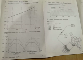
You mean it simulates the variable human torque output with pedal strokes? Or the actual torque sensor generates such voltage at constant torque?
 
You mean it simulates the variable human torque output with pedal strokes?
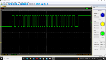
Yes, I simulate the torque waveform that's sent from the torquesensor while riding. Sadly my BB sensor went up in smoke yesterday, I wanted to check, if there are 32 pulses or 32 changing edges (=16 pulses) on the green wire whithin one crank revolution....
This is a picture from an E-Rider sensor but the waveform should be the same with the Bafang.

1764404559541.png

Edit:
I tested it with a constant torque voltage again, now it works with the hubmotor motor contoller and my Shenyi middrive on my test bench with load also. The power is changing with cadence and with torque, so everything as expected. The motor only engages, if the speed signal is higher than 6kph. This Bafang firmware behaviour is really strange...o_O

I think we would need much more testing with different firmwares, firmware settings and different motors, to find dependencies. At the moment it looks simply chaotic :unsure:

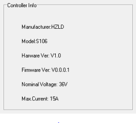
This is the controller I'm testing with:

1764420924206.png
 
Last edited:
Sadly my BB sensor went up in smoke yesterday
Got a working torquesensor from a G330 now. There are 32 pulses per revolution on the green wire. So I have updated the repo with this logic, having one half wave per 16 pulses. But I have not released a V0.4 with a precompiled hex file, as there will be no user anyway ;)

This are the pulses of one crank revolution. Not 360° exactly, just turned the crank once by hand.
1764788321810.png
 
Last edited:
I use it :) Last Sunday we talked about it and then on your recommendation i changed it to "having one half wave per 16 pulses" because the G330 did not like the "back to constant torque signal". On github the map " .settings " is still ok as is ? Because with previous changes to the main.c i think the map .settings was changed too?
 
Hi Stancecoke,

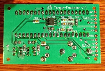
I designed a circuit board for the emulator. The circuit is identical to your board, but the Bluepill module is different. I'm more familiar with ESP and ATmega, and the ST development environment is new to me. The emulator works, but I'm not getting any signals on the CAN bus. A11 and A12 remain at a fixed level. Do you have any ideas? The software is your version 0.3.
Bottom.jpgTop.jpg
 
Back
Top