• Hello ES! We could use some help to get us past the finish line on building the new knowledgebase for the forum.
    Can you donate? Please see our fundraising page. Thank you!

Nissan Leaf motor at 60V, 1/6 the power?

Also, beware of just looking for higher power reading on the VESC tool. You want to get the highest output power for your input power. VESC only shows input power. So optimised for rpm x torque.
As it's a dyno, I also have data from the regen motor.
From remember there is something like 20-25% lost between battery current from leaf input to ME1507 output, but I think I will monitor this more precisely.
 
Additionally, try the motor simulator. It takes some getting used to, Benjamin has not made it particulary intuitive,
I looked at this and effectively, motor analysis seem way to complex for my level of understanding.

From remember there is something like 20-25% lost between battery current from leaf input to ME1507 output, but I think I will monitor this more precisely.
Tried some other tests to determine overall efficiency from my dyno (two motors).
I keep RPM around 1000 and play with pA of the regen motor (ME1507).

Test at 59V
Regen motor 300pA and 66A battery
Leaf motor 84A battery.
So, around 78.6% efficiency

Regen motor 400pA and 82A battery
Leaf motor 107A battery.
So, around 76.6% efficiency

What can be approximately the efficiency of each motor?
My guess, and expectation, is the ME1507 is really inefficient managing 300 and 400 pA at only 1000 rpm.
 
I looked at this and effectively, motor analysis seem way to complex for my level of understanding.


Tried some other tests to determine overall efficiency from my dyno (two motors).
I keep RPM around 1000 and play with pA of the regen motor (ME1507).

Test at 59V
Regen motor 300pA and 66A battery
Leaf motor 84A battery.
So, around 78.6% efficiency

Regen motor 400pA and 82A battery
Leaf motor 107A battery.
So, around 76.6% efficiency

What can be approximately the efficiency of each motor?
My guess, and expectation, is the ME1507 is really inefficient managing 300 and 400 pA at only 1000 rpm.
That doesn't sound too bad tbh. That's like 88% efficiency per motor and inverter, which is kind of normal...

Post your parameters for the FOC setup, I'll throw them into the simulator. I've spent a lot of time recently trying to get as much as possible out of a particularly strange motor without enough battery voltage... Kind of interesting to see how your one lines up with simulation.
 
1763482220223.png

This is the results you get from the simulator. I found it quite accurate compared to the motor I was trying to wrangel more power out of, though quite optimistic; it does not seem to do a great job of accounting for steady state losses. I put 69V being 1.15x bus voltage since it does not account for overmodulation.

You just use your parameters, and in additional info add the number of poles (8 for Leaf motor).
 

Attachments

  • 1763481413696.png
    1763481413696.png
    247.3 KB · Views: 7
Last edited:
😲😁 really nice! Thanks for that.
18 kW and 158 Nm peak. I like it. Sound perfect for my solar catamaran application.

-Where is the peak power? 750 rpm or over?
-How to obtain this in reality? Despite pA set at 400A, I never see more than 276 pA.
 
😲😁 really nice! Thanks for that.
18 kW and 158 Nm peak. I like it. Sound perfect for my solar catamaran application.

-Where is the peak power? 750 rpm or over?
-How to obtain this in reality? Despite pA set at 400A, I never see more than 276 pA.
You should take this with a pinch of salt. This is the optimal case.

Why did you never see more than 276 pA? Ummm how are you measuring it? I can't help but notice 276xsqrt2 is basically 400... Are you using a clamp meter with rms?

Otherwise, maybe your generator cannot provide enough torque?

I suggest that now you can see how to use the motor sim, have a go yourself and start poking things.

Did you get the encoder running? With that motor, all bets are off if you're running sensorless.
 
Incidentally, the torque a motor can generate before reaching magnetic limit is proportional to its rotor's "volume" or integral r².dl. About 200Nm/L is realistic. The leaf motor has a rotor of 130mm diameter and 150mm long. 2L. Around 400Nm is the likely total magnetic saturation.
 
VESC soft.


No.
Between the problems (incompatibility?) with the MT6816 and the fact I don't know if the MT6701 or the AS5047P will work, I still test sensorless.
Seriously not as5047

The mt6816 you have is supported. Try it.
 
I'm designing my Catamaran 16S 102 kWh batteries from Caddy Lyriq modules.
It seem wise to design with a BMS compatible with VESC controller.
Is the Trampa VESC BMS can be a good idea?
The two batteries will charge at 90A max and discharge at 200A max. Sure the Trampa BMS can't do this, but is it possible to use it as monitoring device compatible with VESC?
I'm open to other idea of VESC compatible BMS.
 
Last edited:
The two battery will charge at 90A max and discharge at 200A max. Sure the Trampa BMS can't do this, but is it possible to use it as monitoring device
Yes, you can bypass cherge/discharge, that is how I run all my builds, I do have a fuse and disconnect breaker though.

I'm open to other idea of VESC compatible BMS.
The Trampa one is supposed to be good.

Here are some Vesc compatible BMS's I know of:
Vesclabs
Jetfleet
ENNOID
Chineese ENNOID rip-off

Or if you want to go the el' cheepo route, I have a project that connects common JBD bms's to Vesc:

Making bms's VESC compatible

 
Yes, you can bypass cherge/discharge, that is how I run all my builds, I do have a fuse and disconnect breaker though.
But if you bypass the charge entirely the BMS won't cut power when a cell is full, depending on the conditions that may not be much of an issue though. Like if you are only charging the battery to 90% and it's fairly well balanced and in good health.

I think you could use the charge output to enable a contactor or similar for charging. That would only disable overcurrent during charging but considering the charger should manage that I don't see why a fuse or circuit breaker shouldn't be enough. I assume the charge output needs to see the battery voltage so I guess you would need a diode there. Not an ideal setup, maybe the BMS can be programed to control the contactor with an output pin and even use additional shunts in parallel so the BMS just reads 1/10 the actual current but there are issues with that as well.
 
:D Thanks! It's exactly the kind of advice I'm looking for.
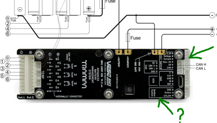
I'm not worry about cells to stay balanced considering high quality GM cells, but I'm worry about overcharge possibility.
In discharge, that seem perfect as the VESC controllers will cut power, but when charge from solar MPPT's of shore power that can cause huge issue.

Also, is two VESC controller and two VESC BMS is too much for the VESC tool?
I mean, ideally, I would like to have V cell min, V cell max, Voltage, battery Amps, SOC, motor power, motor temp, motor RPM on a screen... and all that for two motors, two batteries.
Is it too much?
 
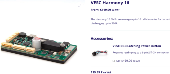
The new VESC Harmony 16 seem nice and high quality, but really, I can't see myself weld battery wires on this BMS.
Seem well design for small motorcycle, but not much for 8 tons catamaran able to discharge at 150-200A for few hours. :unsure:
 
I think you could use the charge output to enable a contactor ... for charging
To me, it's the best way and it kind of look possible based on data sheet.
Anyone have more information about ''external power switch''?

1769087658136.png

1769087736706.png
 
I think the "Button Switch" sounds like it's for a switch that you can use to turn power to the ESC on and off, hence the LED_SW which is probably for an LED on the switch to light up when it's on.

The inputs for an external shunt though seems to indicate there is a way to have an external contactor, since why would use you an external shunt other than to pass more charging power than the internal shunt can handle so that would indicate that's more power than the internal charging FETs can handle too.

I think maybe the "EXT Switch" area might be what you are looking for? If there isn't anything about that port in the documentation I would ask VESC labs about it.
 
Thanks for your input Scianiac. It's exactly what I think of the external functionality of this BMS.
Sadly, manual don't give much information about this.
I would ask VESC labs about it.
I'm not sure VESC labs support Trampa stuff even if they create it few years ago.
Anyway, I wrote to info@Trampaboard and I hope they can clarify this.
 
Thanks for your input Scianiac. It's exactly what I think of the external functionality of this BMS.
Sadly, manual don't give much information about this.

I'm not sure VESC labs support Trampa stuff even if they create it few years ago.
Anyway, I wrote to info@Trampaboard and I hope they can clarify this.
for some reason my head autofilled that picture being of the VESClabs BMS
 
I think you could use the charge output to enable a contactor or similar for charging.
I have thought about that solution too, but I worry that if the bms only cut the charge mosfets the contactor might still stay closed off the discharge fets :unsure:
 
for some reason my head autofilled that picture being of the VESClabs BMS
I would like to use the VESC labs BMS, but this one seem well design for small motorcycle instead of my Catamaran application.
Limited to 15A charge and ''up to'' 320A discharge (so, 100A continuous?)... not a great match for me.
And to add, I don't see how I could hook a contactor on this BMS to bypass the fets :confused:

1769171999952.png
 
Answer from Trampa about the BMS external power switch 😕

There is no more development for the Trampa VESC BMS, unfortunately the external power switch function does not work. You will need to make your own solution for that.
Sad. Comprehensive, of course, as Vedder and probably some other brilliant peoples have left Trampa to start VESC labs.
I don't know what to do. I'm really interested to build my batteries with a VESC compatible BMS.
 
I would ask VESClabs and Ennoid about their options and just see what they say about being able to handle higher charge currents. They are both quite development heavy so may have a solution or be willing to add one. Your application doesn't exactly seem that uncommon and will only be more common even in smaller vehicles as higher power batteries can charge faster. Like I think I would want more than 15A charge in a mid sized or even small E-moto.

Or of course use a massive JBD BMS with the open source connection software to hook it up to VESC.

Honestly I think Trampa may be dead unless they find some talent to do some development work. Like you can't sell ESCs at their price bracket without them being high quality when there are other competitors in that price bracket that know what they are doing and there are of course so many cheap brands who don't know what they are doing but they are very cheap.
 
Back
Top