• Hello ES! We could use some help to get us past the finish line on building the new knowledgebase for the forum.
    Can you donate? Please see our fundraising page. Thank you!

Nissan Leaf motor at 60V, 1/6 the power?

I would like to use the VESC labs BMS, but this one seem well design for small motorcycle instead of my Catamaran application.
Limited to 15A charge and ''up to'' 320A discharge (so, 100A continuous?)... not a great match for me.
And to add, I don't see how I could hook a contactor on this BMS to bypass the fets :confused:

View attachment 383668
The harmony 32 can be used for 12...16... 32s and carries much higher current. Is that useable for you?
 
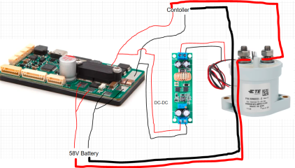
Is that can work in order to use the VESC 16S BMS, but bypassing the mosfet to allow my need of 100A charge and 250A discharge?
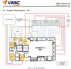
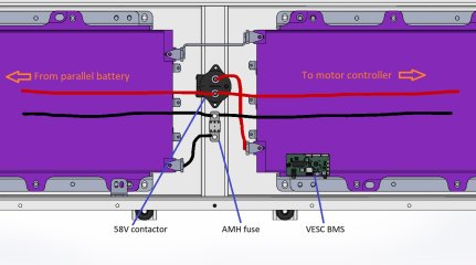
I also joint typical wiring diagram limited to 15A charge.

1769864554606.png


1769864665376.png
 
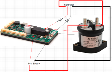
Ummmm! I don't even need DC-DC as contactor with 58V coil voltage are available :)
1769864978851.png
 
That probably works tbh but you'd need to remove the link between the vbms and the controller otherwise i don't think it would ever turn off
 
Is it because current between VESC device will not match?
My goal is to have the battery protect from overcharge from MPPT or grid (charger) and protect from over discharge.
If this contactor bypass work for over charge, but won't work for over discharge cause of no communication between VESC ESC and VESC BMS, I'm ok with that.

I'm clearly concern about the BMS:
  • Built-in power switch with 1A constant current precharge circuit
Is this will still work despite I'm bypassing the fet's?
 
Last edited:
My concern:
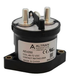
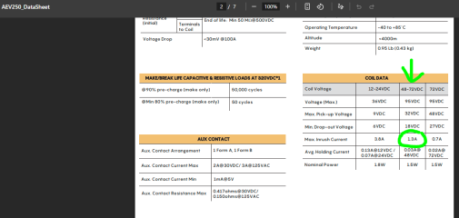
If I understand correctly, the contactor need up to 1.3A to close and the BMS precharge at only 0.8A...

1769958504919.png
1769958541860.png
 
What he means is if you wire it how you show, once the contactor is on it will just be feeding power back to itself so will be latched on.

The precharge not being enough will probably mean the contactor just won't fire until after the precharge phase, idk how the precharge works, does it limit the current until the output voltage to the controller is to a fixed point or is it timed based.

If you just only wire the BMS to the contactor and not to the controller it will solve the latching the contactor on problem but you will have no precharge function. If you wire it like you have but install a diode so to the contactor cannot power itself as I mentioned a few posts back that would work and the precharge may work probably just not quite as well as inteneded depending how it works because the the contactor is sucking up some of the power but the contactor won't draw 1.3A right away. The precharge will limit the current to 0.8A which means the contactor plus the capacitors in the ESC will mean starting at a low voltage (where the contactor will no draw much current) and then increase as the capacitors get charged, doing the pre-charging and as that happens the contactor will draw more power maybe triggering in that phase but probably at a point the capacitors are already charged enough. The timing of all that depends on how the precharge system works.
 
it will just be feeding power back to itself so will be latched on.
Oh! I catch it. So, yeah, with a diode (or two?) between controller and contactor coil that can work.

idk how the precharge works, does it limit the current until the output voltage to the controller is to a fixed point or is it timed based.
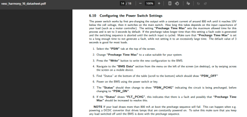
Based on BMS spec sheet: pre-charging the output with a constant current of around 800 mA until it reaches 10V below the cell voltage.
It's adjustable via “Precharge Time Max” in VESC tool and default value is 3 sec.
I will have two batteries in parallel and I bet worst case a single battery will precharge everything. That mean: 2 VESC ESC, 4 MPPT, 1 DC-DC and a Victron Multiplus-II.
I bet it's quite a lot of capacitance.
Still, I think it's not a big deal if it's long as I would need to precharge only few time a year as the rest of the time all the system will stay ON.

I think my biggest problem can be if the contactor can close with as little than 0,8A and scrap the precharge.
Is it possible to simply slow down contactor closing procedure?

BTW, thanks a lot for your inputs guys, I lean a lot and can go foward with this project.
 
Hey!! Wait a minute. This VESC BMS can only charge at 15A because it have separate port for charge and discharge port (up to 320A).
What if I simply use it as common port and connect my MPPT's and charger directly on controller output (Pack+/Pack-)? 🤔
 
You can always just install a manual precharge button for the times you hook it back up.

No you can't use the discharge port, I mean you can it will charge just like regen but it won't be able to stop the charging which is kind of the whole point. The body diodes of the big Mosfets will just allow current to flow even when they are turned off. Common port BMS have two mosfets wired in series in opposite directions to solve this.
 
So, if I've understand everything correctly, I can use the VESC BMS 16S with a contactor to allow my need of 100A charging and 250A charging.
Downside:
-Coulomb counter is screwed.
-SOC only related to Volts.
-Contactors consumption up to 0,08 kWh / day 😬
-Precharge can be compromise (manual precharge can be need).
-Non polar contactor is needed as it can open under charge or discharge
-Other?

Advantages:
-VESC ecosystems (ESC, BMS and display)
-Absolutely extra compact BMS (3''x1,5'')
-Other?
1770040023858.png
 
You only need one diode on the positive.

You could install a second shunt in parallel with the one on the BMS, say 1/10th (or would that be 1/9th, eh calibrate it anyway) the one on the VESC and so the coulumb counter should read some multiple of the real and SOC based on columbs would work if you set it to 1/10 what it actually is in the BMS.

The BMS really isn't very small when you factor in the size of the contactor.

Also many other non-VESC BMS have displays you can hook up and you can get those in any current rating you want, I kinda think just using one of those may be a better option, even using one that can be hooked up to the VESC with a translator board/program.
 
many other non-VESC BMS have displays you can hook up and you can get those in any current rating you want, I kinda think just using one of those may be a better option
I'm open to suggestion.
I was planning to use JBD contactor BMS (JBD-AP21S002), but:
-I don't trust them much. The contactor is not that large and I don't know how well it can open in discharge, but also in charge.
-300mA consumption 😲 Wow! that near 1 kWh/day for two BMS.
-The app kind of work well... most of the time... when it don't freeze and stop communicating.

VESC tool with a reliable large contactor seem better to me, but I'm clearly open to suggestion.
 
I have a similar project, sailing boat Wibo 930.The engine is an SMG180/120 from smart ED13.I also tried Vesc but the engine didn't run well with it.I converted it from a resolver to an RLS RMB29 Sin/Cos encoder and run it with Sevcon Gen4 size 6. So it runs really well.Battery is Li-ion 16s 600AH.
 
I have a similar project, sailing boat Wibo 930.The engine is an SMG180/120 from smart ED13
Noooo! Nice! Where is it possible to see details of the build?
My first test to spin an EV motor with a low voltage controller was with a Smart motor :D
It spun well.

With Sevcon you can use Victron on Cerbo gx.
Yes, I learn this few weeks ago.
But do your think the Victron display can work with a Catamaran... well, I mean two motors?
 
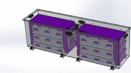
Not exactly related to motor-controller-technology, but here is the 16S battery I plan to build out of a Caddy Lyriq battery.
51 kWh, so two in parallel will give us 102 kWh.
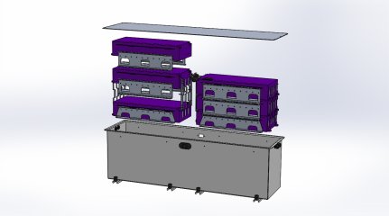
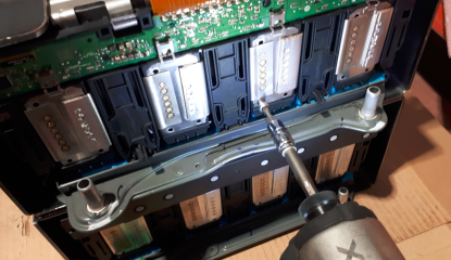
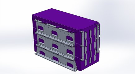
To connect 6 modules to 1 VESC BMS, I have to connect 3 modules in parallel at cells level with busbars.
GM start with three 97Ah cells welded together to create a 291Ah cell. Then, I create a 873Ah cell out of 9 cells.

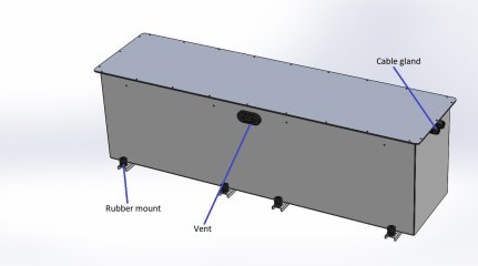
Battery measure 60''x15'', roughly 640lbs (each module is 84 lbs).
I will have to assemble it inside the boat 😉
Everything is aluminum. The battery box, the supports, the busbars.

Battery 51 kWh-2.JPG

Battery 51 kWh-3.JPG
Battery 51 kWh-7.JPG
Battery 51 kWh-4.JPG
Battery 51 kWh-6.JPG
1770921282116.png
 
Yes, my ship is marked STD.

I'm far from a programmer or passionate by electronic ship, so clearly I would like to simply find encoder who work with my VESC.
I just tested exactly that encoder you got with a VESC based controller and it works no problem. Here are the settings and calibration process for this encoder


Ok, I effectively have problem with the MT6816 encoder.
It look like VESC detect something as it seem to detect encoder ratio (2147,5).
Two thing I'm not sure:

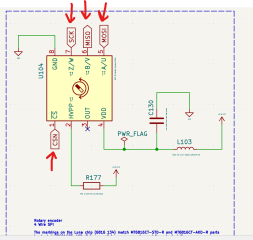
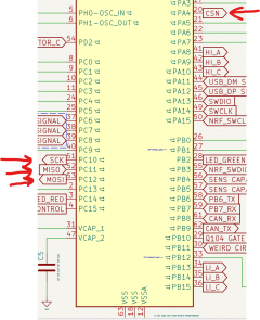
1-Encoder connections. MOSI = V+. See 3e pic. There is a MOSI on the MT6816. Is I have to connect it to V+ or no?
I've connect VCC to V+, CSN to CN... right?

2-How to set encoder on VESC? Simply select MT6816 in General Motor setting/sensor, select encoder in FOC Sensor mode and run Detect encoder... or there is a specific way?

Here are the connections


1782239311202.png

1782238225894.png

You need to ask the VESC Labs to provide you with the full schematic of the controller you use, not just the external connectors pins names because of who knows what those names mean and how those are connected internally.
 
Last edited:
Just finished reading this thread, watching with interest as I want to convert my Broom 35 motor cruiser to EV & I'd like to use Nissan leaf motors to do it for all the reasons already covered but mainly the low cost of the motors and availability. The motors will replace 2 x 120hp Ford diesels, ironically they will sell and probably fund most of the EV build, The space I will save will be incredible & no more smelly dirty engine room & bilge.
I plan to run at 96v as 48v batteries are easy to source but not set in stone.

Which motor controller have you decided to use on your build?
Have you come across this before?
https://www.onlinnissan-leaf-em57-electric-motor-divorced-output-coupler/
 
Back
Top