Pajda
10 kW
Test eqiupment:
- NEWARE BTS-4000 test system with T-type thermocoupler module
- The cells are connected to the tester by Micro-TIG welded Cu strips with a cross section of 6 mm2 with separate sense wires for 4W connection
- Tested in room with relatively stable temperature RT: 20 ±3 °C
Test settings:
- The CC-CV method is used for charging, but the charging process is terminated by a time here, for example 4C charging is terminated after 15 min, 3C after 20 min, .., 1C after 60 min. The consequence of using this method is that the cell is never charged to 100% SoC due to the internal resistance of the cell. The higher the charging C-rate the lower the SoC is achieved.
- For discharging, the standard CC method (3C discharge-rate for all tests) is used, with common termination voltage of 2.5 V
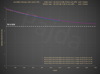
1000 cycle chart
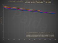
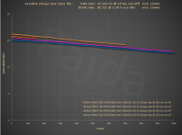
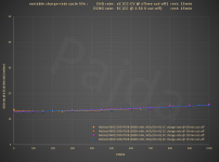
Chart below shows dT = Tend - Tstart (The difference between the cell body temperature at the beginning of the charging which is RT: 20 °C with up to 3 °C tolerance and the body temperature reached at the end of the charging). As a Temperature sensor is used NEWARE T-type miniature (0.2 mm) thermocouple, attached with kapton tape.
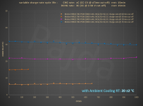
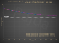
2000 cycle chart
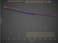
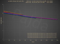
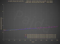
Chart below shows dT = Tend - Tstart (The difference between the cell body temperature at the beginning of the charging which is RT: 20 °C with up to 3 °C tolerance and the body temperature reached at the end of the charging). As a Temperature sensor is used NEWARE T-type miniature (0.2 mm) thermocouple, attached with kapton tape.
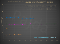
Chart below shows nominal capacity@energy test (according to IEC, the fully charged cell is discharged with 0.2C discharge-rate, for P50B it is 1 A). This test is inserted each 50 test cycles (100 test cycles above 1000 test cycles). The nominal capacity test is used, among other things, to determine the SoH, where the chart shows a level of 70% SoH (for the P50B, 100% SoH corresponds to 4.85 Ah or 17.5 Wh)
CC-CV charging: Voltage & Current & Capacity & Temperature charts
Test eqiupment:
- Professional Battery Test System with T-type thermocoupler module
- The cells are connected to the tester by Micro-TIG welded Cu strips with a cross section of 6 mm2 with separate sense wires for 4W connection
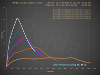
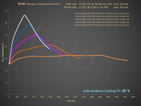
- Tested in professional Temperature Chamber (TC) with 100 l of internal volume with no air flow. Cell sample was pre-conditioned to test temperature which was very stable during the test TC: 25 ±0.5 °C (different temperature than the cycle life test)
Test settings:
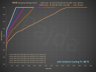
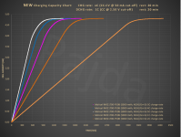
- The CC-CV method is used for charging to 100% SoC, the charging process is terminated by cut-off current 50 mA here,
- before each charging test, the cell was discharged by 5 A current to 2.5 V cut-off voltage.
New:

- NEWARE BTS-4000 test system with T-type thermocoupler module
- The cells are connected to the tester by Micro-TIG welded Cu strips with a cross section of 6 mm2 with separate sense wires for 4W connection
- Tested in room with relatively stable temperature RT: 20 ±3 °C
Test settings:
- The CC-CV method is used for charging, but the charging process is terminated by a time here, for example 4C charging is terminated after 15 min, 3C after 20 min, .., 1C after 60 min. The consequence of using this method is that the cell is never charged to 100% SoC due to the internal resistance of the cell. The higher the charging C-rate the lower the SoC is achieved.
- For discharging, the standard CC method (3C discharge-rate for all tests) is used, with common termination voltage of 2.5 V
1000 cycle chart


Chart below shows dT = Tend - Tstart (The difference between the cell body temperature at the beginning of the charging which is RT: 20 °C with up to 3 °C tolerance and the body temperature reached at the end of the charging). As a Temperature sensor is used NEWARE T-type miniature (0.2 mm) thermocouple, attached with kapton tape.

2000 cycle chart


Chart below shows dT = Tend - Tstart (The difference between the cell body temperature at the beginning of the charging which is RT: 20 °C with up to 3 °C tolerance and the body temperature reached at the end of the charging). As a Temperature sensor is used NEWARE T-type miniature (0.2 mm) thermocouple, attached with kapton tape.

Chart below shows nominal capacity@energy test (according to IEC, the fully charged cell is discharged with 0.2C discharge-rate, for P50B it is 1 A). This test is inserted each 50 test cycles (100 test cycles above 1000 test cycles). The nominal capacity test is used, among other things, to determine the SoH, where the chart shows a level of 70% SoH (for the P50B, 100% SoH corresponds to 4.85 Ah or 17.5 Wh)


CC-CV charging: Voltage & Current & Capacity & Temperature charts
Test eqiupment:
- Professional Battery Test System with T-type thermocoupler module
- The cells are connected to the tester by Micro-TIG welded Cu strips with a cross section of 6 mm2 with separate sense wires for 4W connection
- Tested in professional Temperature Chamber (TC) with 100 l of internal volume with no air flow. Cell sample was pre-conditioned to test temperature which was very stable during the test TC: 25 ±0.5 °C (different temperature than the cycle life test)
Test settings:
- The CC-CV method is used for charging to 100% SoC, the charging process is terminated by cut-off current 50 mA here,
- before each charging test, the cell was discharged by 5 A current to 2.5 V cut-off voltage.
New:


Last edited:

