10S custom skate ESC: testers wanted!

erwincoumans said:
I have been experimenting more with the VESC (thanks to silviasol build) and most works fine, but I have some question about parameter tuning for 'current' control: the motor spins up immediately from 0 to max current at the slightest move of the controller. When using 'duty cycle' it works fine, gradually faster rotating motor from 0 to max.

What is/are the best parameters to tune in the BLDC tool to make 'current control' work less extreme/more gradual?

Also, I hooked up the VESC to a computer PSU, the +12V lead provides up to 125 AMP, up to 1500Watt (http://www.amazon.com/Corsair-AX1500i-Titanium-Efficiency-CP-9020057-NA/dp/B00MFJ4OBA/ref=sr_1_1?ie=UTF8&qid=1428940650&sr=8-1&keywords=1500watt+psu for about 400$). This works great, as long as you don't push the limits. If you exceed the limit, the PSU simply shuts off, and you can restart after a few seconds.

Is everyone using batteries to test their ESC/brushless motors on the bench, or are the affordable (<500USD) bench power supplies that supply 12V at over 100AMP?

If you have no load on the motor and use current control, it will spin up to max rpm and that is the correct behaviour. If you are driving and thus have load on the motor, the current or torque will correspond to the amount of acceleration you apply, regardless of the speed you have. So regardless if you run at 5 km/h or 20 km/h, a given amount of input on the stick will correspond to the same acceleration in both cases. This feels a lot more natural while driving than other modes. Duty-cycle mode with active freewheeling (or regenerative braking) will feel very weird while driving, since a small input on the stick while driving fast will actually cause braking. I strongly recommend to use current control.
 
vedder said:
erwincoumans said:
I have been experimenting more with the VESC (thanks to silviasol build) and most works fine, but I have some question about parameter tuning for 'current' control: the motor spins up immediately from 0 to max current at the slightest move of the controller. When using 'duty cycle' it works fine, gradually faster rotating motor from 0 to max.

What is/are the best parameters to tune in the BLDC tool to make 'current control' work less extreme/more gradual?

Also, I hooked up the VESC to a computer PSU, the +12V lead provides up to 125 AMP, up to 1500Watt (http://www.amazon.com/Corsair-AX1500i-Titanium-Efficiency-CP-9020057-NA/dp/B00MFJ4OBA/ref=sr_1_1?ie=UTF8&qid=1428940650&sr=8-1&keywords=1500watt+psu for about 400$). This works great, as long as you don't push the limits. If you exceed the limit, the PSU simply shuts off, and you can restart after a few seconds.

Is everyone using batteries to test their ESC/brushless motors on the bench, or are the affordable (<500USD) bench power supplies that supply 12V at over 100AMP?

If you have no load on the motor and use current control, it will spin up to max rpm and that is the correct behaviour. If you are driving and thus have load on the motor, the current or torque will correspond to the amount of acceleration you apply, regardless of the speed you have. So regardless if you run at 5 km/h or 20 km/h, a given amount of input on the stick will correspond to the same acceleration in both cases. This feels a lot more natural while driving than other modes. Duty-cycle mode with active freewheeling (or regenerative braking) will feel very weird while driving, since a small input on the stick while driving fast will actually cause braking. I strongly recommend to use current control.

Hi Vedder I've sent you a mail, please check your mailbox when you have time for it :wink:
 
vedder said:
I strongly recommend to use current control.
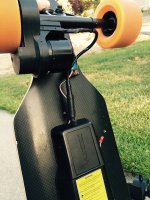
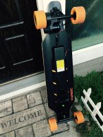
Thanks vedder. OK, I enabled current control and embedded the VESC inside the Yuneec E-Go with its original motor. Luckily the VESC fits inside the original enclosure of the ESC, including the large capacitor on the cable.

The first test ride worked great and it can reverse now. I haven't hooked up the motor sensors yet. Here some pictures of the VESC controller inside the E-Go.
View attachment 2

vesc_ego2.jpg

vesc_ego3.jpg

Now the VESC fine tuning starts, and increasing the E-Go maximum speed (possibly with a new motor).

Oh, it would be nice to have current control with break and reverse, like the Boosted Board. Reverse only kicks in once the controller is released from braking at zero velocity.
 
Nice that you got it running!

Reverse only kicks in once the controller is released from braking at zero velocity.
Currently the VESC cannot do active braking (putting power into the motor to slow it down) in the sensorless mode. That is why the brake force is quite weak close to zero speed. Only regenerative braking is possible. As soon as you stop, you will get full torque in the other direction. I'm trying to implement sensorless active braking in firmware, but it is quite difficult. If you connect the sensors active braking should work.
 
Regenerative braking is strong enough for me.

Does the VESC already have support for nRF24L01 tranceiver? Which pins do you hook it up?

Aside from supporting wireless remote control, an RF24L01 usb dongle (crazyradio) could allow a fully wireless BLDC tool.
 
erwincoumans said:
Regenerative braking is strong enough for me.

Does the VESC already have support for nRF24L01 tranceiver? Which pins do you hook it up?

Aside from supporting wireless remote control, an RF24L01 usb dongle (crazyradio) could allow a fully wireless BLDC tool.

The nrf24l01 is supported, but the implementation is quite limited. It only listens for one packet which emulates input for the nunchuk implementation.

If you would like to run BLDC Tool wirelessly, you could use UART and a bluetooth module. That implementation is complete, so if you activate the UART application using USB and connect a bt module that uses the rfcomm profile, you could connect to it using bldc tool as it is.
 
Awesome work vedder! It's exciting to see your VESC being implemented into custom AND commercial eboards! I can't wait to hear how the VESC has changed peoples daily commute, recreational rides, and overall performance of their boards.

Hopefully people continue to contribute their VESC experiences here!
 
torqueboards said:
Nice... @ Erwin - What controller are you using for your E-go now?
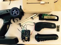
Various, my current favorite is the Sony Move controller (bottom right in picture), connecting to an Arduino+USB host shield+Bluetooth dongle,
hooked up as servo control to VESC. Instructions are here: https://barrettsprojects.wordpress.com/2013/01/13/driving-an-rc-car-with-a-ps3-controller

My first test of VESC was using a simple Exceed-RC transmitter+receiver, that worked just fine but too bulky, I may make it smaller using 3d printing enclosure, as described on this wonderful forum. Silviasol soldered 3 pins on my VESC, so the standard receiver cable plugs right in.

Then I experiment with some motorized faders, simulating the spring using force feedback, and communicating over nRF24L01+ tranceivers.
See 'FireFader' instructions here: http://www.openhaptics.org (Currently I use a 100mm version, but I intend to use a smaller motorized Fader)

I may embed a tiny IMUDuino into the Boosted Board controller: the IMUDuino has BLE and also 10-DOF IMU (see in the picture on the right).
http://femto.io/products/imuduino

FullSizeRender-14.jpg
 
Vedder :arrow: Seeing that you haven't contacted me back even after more than a week where you did answer kindly Erwin , I assume that either you did not receive my mail or you didn't feel the need to answer me.

Knowing that mailboxes are not failure proof I'll choose to think that it is just the first solution. By the way I studied a lot these past days and came up with something way more simple and efficient than everything I explained to you. Please allow me to ask directly here instead :

-I want to input more than one signal to the ESC.
I know that you have put different ports, for Hall sensors and for analog or digital transmission for a RC transmitter or a Bluetooth like dongle. Plus the plug for BDLC tool.

Can I simultaneously use multiple ports on the ESC for throttle signals or does it deactivates one port when another one is used ?

About the Hall sensor port, can I plug any sensor type in it instead and just write on firmware to get the wanted info ?

Maybe I'm not the only one interested in these characteristics.

Onloop & Jacob :arrow: No news from you since the promising teaser videos, only got partial infos about hardware possible changes for Vedder himself since he wants to plug more voltage and needs more heat dissipation. So can you please guys give us updates on schedule ?

It is beta VESC after all, we can accept if you encounter troubles during tests but it would be fair to get input from time to time instead of months to months.
 
Vanarian said:
Vedder :arrow: Seeing that you haven't contacted me back even after more than a week where you did answer kindly Erwin , I assume that either you did not receive my mail or you didn't feel the need to answer me.

Knowing that mailboxes are not failure proof I'll choose to think that it is just the first solution. By the way I studied a lot these past days and came up with something way more simple and efficient than everything I explained to you. Please allow me to ask directly here instead :

-I want to input more than one signal to the ESC.
I know that you have put different ports, for Hall sensors and for analog or digital transmission for a RC transmitter or a Bluetooth like dongle. Plus the plug for BDLC tool.

Can I simultaneously use multiple ports on the ESC for throttle signals or does it deactivates one port when another one is used ?

About the Hall sensor port, can I plug any sensor type in it instead and just write on firmware to get the wanted info ?

Maybe I'm not the only one interested in these characteristics.

Onloop & Jacob :arrow: No news from you since the promising teaser videos, only got partial infos about hardware possible changes for Vedder himself since he wants to plug more voltage and needs more heat dissipation. So can you please guys give us updates on schedule ?

It is beta VESC after all, we can accept if you encounter troubles during tests but it would be fair to get input from time to time instead of months to months.

Sorry about not replying until now, but I cannot find your email. If I haven't answered for a few days, feel free to remind me. Even if I receive the email, sometimes I miss answering them since I get 10-20 emails every day with questions about my ESC.

Can I simultaneously use multiple ports on the ESC for throttle signals or does it deactivates one port when another one is used ?
You can, but it depends which ports. USB and CAN are always active. Using USB, CAN and UART simultaneously is also possible. If you use PPM simultaneously with anything else, the PPM implementation will override the latest input with the last seen ppm pulse once you get a new input, even if there is no PPM signal present. I can update the PPM application to ignore the last PPM pulse when nothing has been received for a while, and then you can use USB, UART, CAN and PPM at the same time.

Regardless which interface you are using, there is a timeout that will deactivate the motor if no new commands have been received for more that a certain period for any interface. So you have to make sure to keep sending commands from some interfaces with higher rate than the timeout interval. You can also adjust the timeout and optionally use braking after a timeout using BLDC Tool:
http://vedder.se/wp-content/uploads/2015/01/BLDC_Tool_app_general.png

About the Hall sensor port, can I plug any sensor type in it instead and just write on firmware to get the wanted info ?
I haven't spent much time on the hall sensor implementation, but it supports hall sensors with 120 degrees spacing. In the sensorless tab of BLDC Tool, there are three parameters for configuring hall sensors:
http://vedder.se/wp-content/uploads/2015/01/MCCONF_Sensorless.png
Direction can be 0 or 1, the others can be 0 to 5. First you adjust direction and fwd add until the motor runs properly forwards, then you adjust rev add until it runs properly backwards.

If I get a setup with hall sensors, I would like to implement so that the sensors are used just when starting up, then sensorless mode is used. However, for my electric longboards, I think I would prefer not having sensors since it works so well anyway and sensors are additional components that can fail.

If you remove and replace some resistors at the sensor port, you can also use a quadrature encoder. I'm working on an implementation for that right now, but I don't know when it will be finished. It is intended mostly for position control for industrial motors, and I also want to use it together with FOC once I finish that implementation.
 
To all VESC BETA testers...

Your VESC has been delayed much longer than we would have hoped but it is definitely coming soon..... it is very common for delays to occur during the manufacturing process the question is how good you are at estimating how long these delays will set you back when you estimate your final delivery date! If you remember my original schedule said delivery at end of april. But then we got off to such a great start and looking like finishing & shipping early april. Well we were wrong. DELAYS & DELAYS.

I know it sux! everyone wants everything yesterday, but i can assure you we are trying to get it done as quick as possible.

More update photos below.

So we decided its best to get some heat shrink put onto the vesc. This way you can prevent blowing them up from shorting against each other.

img-3893.jpg

img-3894.jpg

img-3895.jpg
 
That's great, how did you do the heat shrink?

Vedder said:
If you remove and replace some resistors at the sensor port, you can also use a quadrature encoder. I'm working on an implementation for that right now, but I don't know when it will be finished. It is intended mostly for position control for industrial motors, and I also want to use it together with FOC once I finish that implementation.
This is very interesting, I can't wait to learn more about this.

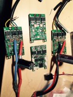
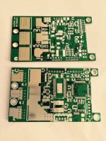
I purchased 10 bare VESC PCBs from Hackvana and components for 10 VESC's from Mouser.
My colleague soldered 3 VESCs, she is very experienced. I tried soldering myself but I failed miserably, it will take a while before I can manage that. On the right is the VESC made by silviasol on this forum, and the 3 on the left by my colleague.

FullSizeRender-15.jpg

You have to be pretty experienced in SMT soldering to assemble those PCBs, so you probably want to wait for the assembled boards from Vedder.

FullSizeRender-17.jpg
 
How are you guys assembling the boards with solder? I built a toaster reflow oven a few weeks ago during my spring break and need to figure out the best way to deal with the larger components. I will be using a stencil to apply the paste since the pitch of pins on the microcontrollers give me some kind of OCD/seizure thinking about it. School be keeping me too busy with finals around the corner in a few weeks...
 
vedder said:
Sorry about not replying until now, but I cannot find your email. If I haven't answered for a few days, feel free to remind me. Even if I receive the email, sometimes I miss answering them since I get 10-20 emails every day with questions about my ESC.

Can I simultaneously use multiple ports on the ESC for throttle signals or does it deactivates one port when another one is used ?
You can, but it depends which ports. USB and CAN are always active. Using USB, CAN and UART simultaneously is also possible. If you use PPM simultaneously with anything else, the PPM implementation will override the latest input with the last seen ppm pulse once you get a new input, even if there is no PPM signal present. I can update the PPM application to ignore the last PPM pulse when nothing has been received for a while, and then you can use USB, UART, CAN and PPM at the same time.

Regardless which interface you are using, there is a timeout that will deactivate the motor if no new commands have been received for more that a certain period for any interface. So you have to make sure to keep sending commands from some interfaces with higher rate than the timeout interval. You can also adjust the timeout and optionally use braking after a timeout using BLDC Tool:
http://vedder.se/wp-content/uploads/2015/01/BLDC_Tool_app_general.png

About the Hall sensor port, can I plug any sensor type in it instead and just write on firmware to get the wanted info ?
I haven't spent much time on the hall sensor implementation, but it supports hall sensors with 120 degrees spacing. In the sensorless tab of BLDC Tool, there are three parameters for configuring hall sensors:
http://vedder.se/wp-content/uploads/2015/01/MCCONF_Sensorless.png
Direction can be 0 or 1, the others can be 0 to 5. First you adjust direction and fwd add until the motor runs properly forwards, then you adjust rev add until it runs properly backwards.

If I get a setup with hall sensors, I would like to implement so that the sensors are used just when starting up, then sensorless mode is used. However, for my electric longboards, I think I would prefer not having sensors since it works so well anyway and sensors are additional components that can fail.

If you remove and replace some resistors at the sensor port, you can also use a quadrature encoder. I'm working on an implementation for that right now, but I don't know when it will be finished. It is intended mostly for position control for industrial motors, and I also want to use it together with FOC once I finish that implementation.

Ok thank you for the infos ;) Well I want to run force sensors instead of RC transmitter and sensorless motors because you are right you did something really progressive with the VESC. I have received a couple of chips already, I can provide you data on this if you want when the ESCs are shipped ? You said that there are unused cycles on the proc so maybe I can put some of them at good use.

onloop said:
To all VESC BETA testers...

Your VESC has been delayed much longer than we would have hoped but it is definitely coming soon..... it is very common for delays to occur during the manufacturing process the question is how good you are at estimating how long these delays will set you back when you estimate your final delivery date! If you remember my original schedule said delivery at end of april. But then we got off to such a great start and looking like finishing & shipping early april. Well we were wrong. DELAYS & DELAYS.

I know it sux! everyone wants everything yesterday, but i can assure you we are trying to get it done as quick as possible.

More update photos below.

So we decided its best to get some heat shrink put onto the vesc. This way you can prevent blowing them up from shorting against each other.

img-3893.jpg

img-3894.jpg

img-3895.jpg

Thank you guys, as I said delay is not a problem as long as you can keep us updated ! I cheer for your work too.

I'm worried a bit about the heatshrink, won't it make the VESC warmer ? For 10-12s with between 86-76A bursts I might need cooling, unless I stack more voltage (and I hope this won't damage motors as long as I lower A). Otherwise for protection against shortcuts and dust or water splashes this is good news.
 
First of all: Wow! Not that I understand all the stuff you are writing and doing, but it looks definitely far, far more advanced than any R/C ESC out there :shock:


If I may add some suggestions:

- Maybe try to separate control board and FETs so that different voltage/current handling options could easily be implemented without the need of a complete re-design. Not sure how feasible that is, just an idea.

- If going for the design with all the FETs on one side, please add 4 holes around the FET area, so that people can mount cooling solutions securely without using glue

- Maybe add some "status beeps" that lets the user know that the ESC is properly initialized and ready to go, just like R/C ESCs have.

- Not sure if it already has this, but I'd find some sanity checks during initialization important, like checking if the throttle input signal is set to "neutral" so that the vehicle doesn't take off uncontrolled when something is wrong with the throttle-stick or the transmitter is wrongly setup etc.

- Could you also add some basic "traction-control"? I realize, for real traction-control you'd need wheelspeed sensors, but I'm thinking of a simple setting that limits how fast the motor can spool up (independent of amp limitation), so that when driving on low-traction surfaces you don't get tires spinning like crazy. I think this would also add some safety for people on skateboards. Otherwise when going through a short low-traction section (like a puddle or something), the board may spin-out if you hit the throttle at the wrong time.
 
Does any of you guys know how much max voltage the FETs can take? In the optimal cooling conditions I mean ! Depending on the answer I can determine a battery setup :D

lizard said:
First of all: Wow! Not that I understand all the stuff you are writing and doing, but it looks definitely far, far more advanced than any R/C ESC out there :shock:


If I may add some suggestions:

- Maybe try to separate control board and FETs so that different voltage/current handling options could easily be implemented without the need of a complete re-design. Not sure how feasible that is, just an idea.

- If going for the design with all the FETs on one side, please add 4 holes around the FET area, so that people can mount cooling solutions securely without using glue

- Maybe add some "status beeps" that lets the user know that the ESC is properly initialized and ready to go, just like R/C ESCs have.

- Not sure if it already has this, but I'd find some sanity checks during initialization important, like checking if the throttle input signal is set to "neutral" so that the vehicle doesn't take off uncontrolled when something is wrong with the throttle-stick or the transmitter is wrongly setup etc.

- Could you also add some basic "traction-control"? I realize, for real traction-control you'd need wheelspeed sensors, but I'm thinking of a simple setting that limits how fast the motor can spool up (independent of amp limitation), so that when driving on low-traction surfaces you don't get tires spinning like crazy. I think this would also add some safety for people on skateboards. Otherwise when going through a short low-traction section (like a puddle or something), the board may spin-out if you hit the throttle at the wrong time.

If I'm correct, the traction control is already working as soon as you have at least 2 motors! If you only have one, you do realize that you cannot get optimal control as the wheels are not lined up. I'm afraid it might also stress the motor if it has to "mini" brake multiple times around a corner to adjust to the non driven wheel.

For the holes around the FET area, I'm not sure to understand what you want to do : isn't it best to channel the air across the whole board (even using mini pipe exhausts outputting a fan's air)?
 
Happy to help.

60V is maximum rating and you should always give an overhead since it is an inductive load you are connecting that will be able to generate voltage spikes.
 
When you say overhead, is 55V enough difference to be safe or is it too close to 60V? I mean if batteries are charged to give total capacity of 55V, the voltage spike should not grow much?
 
I am not experienced enought in analog design to give any advice but I am sure that Vedder has set the 12s as a realistic limit.
You can always try it out and be sure to log all voltages with the bldc tool. Optionally you could look at spikes on the phase lines in different load conditions with an oscilloscope.
 
When connecting the VESC to a hobby RC-receiver (3 servo pins), the decoded PPM value is around 50%, which is OK.

When I use the Arduino Servo library (on Arduino Uno), the decoded PPM value is 23% at the center, using default "Servo.write(90)".
The pulse width on an oscilloscope is the same for both RC-receiver and Arduino: about 1.45ms.
The only difference I can find is that the Max voltage is 2.4V for Arduino and 3.52V for RC-receiver.

When the Arduino Uno is powered by 9V battery (instead of USB 5V) then the BLDC tool shows 33%.

Anyone knows why the VESC servo input signal is sensitive to the voltage, instead of only using the pulse width?
Thanks!
Erwin
 
Vanarian said:
If I'm correct, the traction control is already working as soon as you have at least 2 motors! If you only have one, you do realize that you cannot get optimal control as the wheels are not lined up. I'm afraid it might also stress the motor if it has to "mini" brake multiple times around a corner to adjust to the non driven wheel.

For the holes around the FET area, I'm not sure to understand what you want to do : isn't it best to channel the air across the whole board (even using mini pipe exhausts outputting a fan's air)?

Yeah, I've read about the traction control with multiple motors, but that won't help with my RC cars, the motors drive all four wheels. But it makes me want to build an RC Car with one motor for the front wheels and one for the rear. No need for a center drivetrain and differential anymore :)


Regarding the cooling: The holes would allow to 'sandwich' a heatsink (plus optional fan) on the ESC, similar like it is done on computer mainboards. Heatsink on the PCB side (must be a flat surface and connected to the other side of the PCB with lots of vias of course), metal plate on the other side with the FETS. Both connected by four screws through holes in the PCB. That would allow for a secure hold of the heatsink without stressing the PCB.
 
- Maybe try to separate control board and FETs so that different voltage/current handling options could easily be implemented without the need of a complete re-design. Not sure how feasible that is, just an idea.

- If going for the design with all the FETs on one side, please add 4 holes around the FET area, so that people can mount cooling solutions securely without using glue

New hardware versions are planned for the future, but currently some other features (FOC, position control, ...) have higher priority now. My biggest problem when working on this is lack of time since I also have a full-time job.

- Maybe add some "status beeps" that lets the user know that the ESC is properly initialized and ready to go, just like R/C ESCs have.
That should be easy to add. I will do that soon.

- Not sure if it already has this, but I'd find some sanity checks during initialization important, like checking if the throttle input signal is set to "neutral" so that the vehicle doesn't take off uncontrolled when something is wrong with the throttle-stick or the transmitter is wrongly setup etc.

There are some sanity checks (e.g. that the motor stops, or brakes if configured so, when no control signal has been seen on any interface for more than a specified timeout), but there is nothing that forces the ppm signal to be in neutral or braking before output is allowed. I will add an option for that and leave the possibility to switch it off in bldc tool.

- Could you also add some basic "traction-control"? I realize, for real traction-control you'd need wheelspeed sensors, but I'm thinking of a simple setting that limits how fast the motor can spool up (independent of amp limitation), so that when driving on low-traction surfaces you don't get tires spinning like crazy. I think this would also add some safety for people on skateboards. Otherwise when going through a short low-traction section (like a puddle or something), the board may spin-out if you hit the throttle at the wrong time.

As has been mentioned, there is traction control based on the motor speed difference if you have more than one motor. Making something acceleration based should be possible and I think it can make a lot of difference for RC cars. I will put it on my to-do list.

When you say overhead, is 55V enough difference to be safe or is it too close to 60V? I mean if batteries are charged to give total capacity of 55V, the voltage spike should not grow much?
On 12s, which is 50.4V on a full charge, I have been getting some spikes close to 60V. Since the FETs have some avalanche ratings the ESC should be able to take some occasional spikes, but I don't know how safe it is operating with so low margins. You can give more than 12s voltage a try, but I cannot promise that it will work. I would prefer to have some margin on the voltage.

When connecting the VESC to a hobby RC-receiver (3 servo pins), the decoded PPM value is around 50%, which is OK.

When I use the Arduino Servo library (on Arduino Uno), the decoded PPM value is 23% at the center, using default "Servo.write(90)".
The pulse width on an oscilloscope is the same for both RC-receiver and Arduino: about 1.45ms.
The only difference I can find is that the Max voltage is 2.4V for Arduino and 3.52V for RC-receiver.

When the Arduino Uno is powered by 9V battery (instead of USB 5V) then the BLDC tool shows 33%.

Anyone knows why the VESC servo input signal is sensitive to the voltage, instead of only using the pulse width?
Thanks!
Erwin

There is a hardware filter on the ppm input, so the edges will be a bit affected by that. 2.4V sounds a bit low, so I don't know how reliable that will be. You can also adjust the timing in bldc tool for the ppm signal.
 
Back
Top