Diamondback said:
would i be correct in saying that a 12s2P (4x 6S1P zippy 8000's) would provide about 50V FOC and 16AH capacity ?
Yes, that is true.
Diamondback said:
i have 15AH in the ping, and so far have not used more than 10AH, but i intend longer rides where the 15AH will be used.
im thinking the 12S2P would be a good replacement as in use, it should be very similar in voltage to the ping ?
as the lipo wont sag as much (or at all) it should be very similar to the ping in use.
Also true. With your current setup you will have very little voltage sag at all.
Diamondback said:
i have a 20A ezee controller on my bike with the ezee geared hub, current is limited to 15A by use of a CA-DP.
current was limited to make best use of the ping (1C discharge rate) and to get more range.
i am very interested in buying one of these "all in one" BMS / charging solutions. as my biggest concern is using
a "octopus" harness and getting the connections wrong

Actually, it is not as bad as it looks.

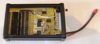
The balance plugs from the four 6s-8000 packs plug into JST-XH connectors in the middle of the board. There are two sets of 2-to-1 5.5mm bullet connector adapters for paralleling the main leads. This will be about as "plug'n play" as we can make it. Basically, you stick a pair of the 6s packs together, with some double-sided tape, do the same thing with the other two 6s-8000 packs, orient them so that the connection ends of each pair of packs face each other in the middle, and then connect the BMS board to the balance plug leads. You then connect the main pack leads to the adapters, stick the special end plates on the ends of the assembled pack and then shrink wrap the whole thing with the provided piece of 9.75" wide PVC shrink wrap.

What you end up with is a 12s2p 48V/16Ah pack that has a full BMS, including cell level LVC protection, cell level over-voltage protection, cell balancing and a charge controller with an automatic end-of-charge cutoff. There will be just three sets of two-wire connections from the pack, two heavy gauge wires for discharge, two medium gauge wires for charging and two very small gauge wires that you either connect into your controller's ebrake input or to the throttle line directly, for the LVC function. For charging, you simply plug in a suitable 48V CC/CV charger or a current limited power supply, and the main LED (at the other end of the pack...) will come on orange, to indicate it is charging. When the cells start getting full their individual red LEDs will start coming on, indicating that the shunt bypass circuit for that channel is active. When all the cells are full, all the red LEDs will be on and then the charge current will be shut off and the main LED will turn green. The shunt circuits will then bleed off all the cells slightly, to the same voltage point, and the red LEDs will all go off. At that point the cells are fully charged and balanced, and the main LED will be green. So, you plug in the charger/supply and simply wait for the main LED to be green and the red LEDs to be all off. At that point you can unplug the charger/supply and the main LED will go off.
Pictures of all this will come next week, once I can get one of these built up. The boards come tomorrow.

-- Gary


