1962 Honda Benly goes electric

Hello! I'm so excited I just found this thread! I too am converting a '60s Benly/Baby Dream to EV! Mine is a '67 CA160, I bought it about a week ago, and it has a seized motor. I think the curvy shape and size of these small '60s Hondas are perfect for EV. Here's mine: https://www.vintagehondatwins.com/forums/showthread.php?2054-CA160-EV-Conversion

Everything you're doing to your build, I have been planning for my own build as well. Same speed and power, even. So this is going to be so helpful! All the advice in here will apply to me as well.

I too will probably use a QS motor. What model number is yours? Is it the 205? What width is the rim? Does the hub fit between the swing arms without needing to widen them?

What happened to the cylindrical shape of the battery box you talked about in one of the first posts? I would like a battery box that is anything but a cube. Even if that means sacrificing range. Something like this would be amazing.

I am still deciding but I'm wondering if I could get enough range out of 25Ah. If I could use 20 LiFePO2 25Ah batteries wired all in series to get 64v 25Ah (1.6kWh) then I think that would be perfect for me. Micah Toll says expected consumption is 50 Wh/mile at 30mph, and 1.6kWh / 50kW/m = 32 miles. And I like LiFePO2 batteries because they'll last forever and are more eco friendly.

But would a lower capacity of 25Ah effect the take off speed that the motor and controller can provide? Will that depend on the controller? I calculate for a 20s1p config: continuous current = 75 amps = 4.8kw @ 64v (nominal) and 5.4 kw @ 72v (max charge). And max current = 125 amps = 8kw @ 64v (nominal) and 9kw @ 72v (max charge). But for the Kelly controller, 160amp is the smallest current that can be selected on their website.

Sorry for all the questions! Keep up the good work! I'm eager to see how fast and quick your bike is once assembled!

Oh and one last thing! I can assure you that 75mph was not the top speed of the original ICE bike. It only had 4 gears and not enough HP. I have a 200cc Honda with 5 gears, new piston rings, and it gets up to 60mph tops, downhill only.
 
mannydantyla said:
But would a lower capacity of 25Ah effect the take off speed that the motor and controller can provide?

The capacity of the batteries doesn't directly determine that. You'd need to know the C rate of the specific model of cells you're using, preferably with an actual discharge curve for those cells at various currents, to guess how much voltage sag they will have at 1p at the current you'll be drawing from them under the conditions of startup (or hill climbing, which is nearly the same).

So let's say you have 2C cells (common for LiFeP04, some are only really 1C despite a 2C rating). They're 25Ah, so it means that 2C x 25Ah = 50A max current draw. (they might survive peaks of higher currents, but sustaining that any lenght of time or repeating it a lot would cause excess heating in the cells, and degrade them faster, as well as sagging in voltage more than staying within the limits).

Let's say you're actually drawing (based on your math below) 125A peak--that would be 5C for a 25Ah cell. If the cell is only a 2C max cell, then you'd be drawing more than double what it was intended to do, and creating more than twice the internal heat, and saggin more than twice as much. If the cells normally sag say, 0.5v each at 2C, they might sag say 1.2v at 5C, which would cut your pack voltage down by a third under load at full charge, and nearly half when nearing empty. (and the emptier the pack is, the worse the sag will be due to higher Ri at lower voltages, etc). The harder you use cells, the lower their lifespan will be. (also, the higher the full charge voltage (HVC), and the lower the stop-discharge voltage (LVC), the lower the lifespan)

Will that depend on the controller? I calculate for a 20s1p config: continuous current = 75 amps = 4.8kw @ 64v (nominal) and 5.4 kw @ 72v (max charge). And max current = 125 amps = 8kw @ 64v (nominal) and 9kw @ 72v (max charge). But for the Kelly controller, 160amp is the smallest current that can be selected on their website.
Unlike pretty much everybody else, Kelly controllers are rated by *phase* current (in the motor side of the controller), but everything you can calculate or measure is *battery* current (in the battery side of the controller), so you won't know for sure what actual battery current will be until you measure it under the conditions you ride under. Calculations can give you a good guess, however.

Max current depends on both controller current limits and actual voltage under that load at the battery, vs system resistances and motor loading. Typically, at least for a moment at startup (and possibly on the full uphill slope of any hill), you'll see a peak current of whatever battery current limit the controller is set for. But voltage on the battery will drop under that load--voltage sag is worse the higher the current is vs the higher the internal resistance (Ri) of the cells is. The C rate of cells is based on that Ri, so the higher the Ri, the lower the C rate.

It's common for LiFePO4 cells to be rated for around 2C. Some, like A123, can handle much higher currents. Many of the other chemistries have more models of cell that can handle higher currents, like the 20Ah EIG NMC cells I'm using (5C continuous, 10C peak for 10 seconds). There are also plenty of salvaged EV packs that are easy enough to disassemble and rearrange into your own pack, that are lower cost than new cells, but still worth doing.
 
Thank you very much amberwolf, and now I realize I am hijacking Mack's thread. I will start my own build thread soon so please don't reply to this here but I just wanted to say that I should have included the specific battery that I am looking at: https://www.electriccarpartscompany.com/Fortune-25Ah-Aluminum-Encased-Battery

I still have a lot of reading and calculating to do. It seems to me that EV builds are more math than wrenching!
 
I"ll reply here for now, then when you make your thread we can move this there. :)

The specs on that page are quoted below (there are multiple sets of specs there, so all are quoted; I've rearranged some stuff so the same stuff is generally together). It isn't all consistent, which would bother me, especially since they specifically claim repeatedly that they are only 2C cells (whcih means the Max Continuous Current is only 2C, or 2x the capacity, which is 2x 25Ah = 50A), but then they say they are 3C for the Max Continuous Current, which would be 75A. A cell can't have two max C-rates, so you should assume these are at best only 2C, or 50A cells (assuming you can trust anything their pages says about their products), and thus I would also disbelieve their 5C (125A) rating.

They don't provide an actual discharge curve, or charge curve, for various rates, so you can't tell what the voltage sag will be for any particular current (until you have them and test for this yourself).

FWIW, for a large-format EV-grade cell, the 1.2mOhm Ri spec isn't too bad, but I'm not sure if I believe it: if they were really a good cell, they should probably be rated for higher currents--EIG NMC 20Ah cells are rated at <3mOhm Ri, but 5C continuous and 10C for 10 seconds.

Aluminum Encased Battery
Aluminum Shell Batteries
LFP Aluminum Shell Battery
Lithium LiFePO4
EV Lithium LiFePO4
ECPC-25Ah-Fortune-Aluminum
25Ah EV, Lithium, LiFePO4,
25Ah EV Lithium LiFePO4 LFP Aluminum Shell Battery Pack
25Ah EV Lithium LiFePO4 LFP Aluminum Shell Battery
25Ah, 3V-3.2V-3.65V, 2C
Fortune 25Ah 3.2V 2C

2.7L * 1.0W * 7.1H in
70 * 27 * 180 mm
1.5 Lbs. / 0.7 Kg
$28.20 16-23
16 - 23 $28.60

NOMINAL/MINIMUM CAPACITY
25Ah @ 1/3C Discharge
MAX DISCHARGE CURRENT (continuous)
75A (3C)
STANDARD CHARGE CURRENT
12.5A (0.5C)
MAX PULSE CHARGE CURRENT (<10 sec)
50A (2C)
MAX PULSE DISCHARGE CURRENT (<30 sec)
125A (5C)
NOMINAL VOLTAGE
3.2
SUGGESTED MAX CHARGE VOLTAGE
3.65
END OF DISCHARGE VOLTAGE
2.2
CYCLE LIFE AT STANDARD (80%)
>2500
INTERNAL RESISTANCE/IMPEDANCE (milliohms)
1.2
SUGGESTED CHARGING CURVE
Constant Amperage to 3.65V,
Constant Voltage,
Decrease Amperage,
Stop at 1A Charge
CHARGE WORKING TEMP F (C)
32 to 122 (-10 to 50)
DISCHARGE WORKING TEMP F (C)
-4 to 122 (-20 to 55)
STORAGE TEMP F (C)
14 to 113 (-10 to 45)
ENERGY TYPE
3V-3.2V-3.65V
 
Hi mannydantyla, Thanks for the new interest, I've been meaning to get back with my progress after a bit of a break.
I took the opportunity of the pandemic to focus on.. very little but the building of my bike...for months! Then things like daily chores, work and money started to become issues. So I took a break to deal with those things and it was a good opportunity to take inventory and realize how far I'd come and to 'see' what was left.

I still have a lot of reading and calculating to do. It seems to me that EV builds are more math than wrenching!

I don't know, lots of both I think. Starting with the bare frame and front wheel of and old ICE bike provides lots of wrenching, re-figuring, fabricating and then some!

The rear wheel width was a big concern for me, there's a link to what I got in the wheel kit reveal post.

Now for an update!
 
OK, finally back to update the build. After obsessing for months on the build my brain began to hurt trying to 'see' what had to happen to tie it all together so I figured a break to wait for the last of the main components was due, especially since the BMS I ordered from Ali Express was going to be 5-6 weeks to arrive.

And it did, with everything I was anticipating it to have.


BMS.jpg


I also decided on the Cycle Analyst for a speedometer and battery gauge,


CA.jpg


And for a charger I went with one from Lunacycle

charger1.jpg
charger.jpg


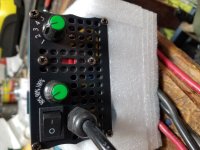
Taking a break helped look at things in a new light and coming back to the gas tank I realized there was a lot of space between it and the frame and with plans to house the DC-DC converter in the tank I could pull all the 12V pos wires out of the headlight an to mini fuse box.


12V breakers.jpg


Time also helped re-figure the speedo mount. (Before the break) I had this idea to make some kind of 3d printed shroud to mount the display. I started to carve a foam mold and mock it up....

mock up.jpg


Not really feeling it when I was looking at the pics, :confused: I needed a new approach.

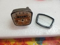
The old speedometer set in from above and had a flange that made a sung fit that I wanted to use. So I thought maybe I could cut off the top and fit a piece of aluminum bar cut to size for a mounting plate.

speedo redo.jpg

top view.jpg
I liked that better,

borg spedo.jpg
kinda like a Borg interface for the new electric machine!


and a few pics of the epoxy mounting to the frame and threaded rod for install

double duty box.jpg
mount.jpg


And lastly to actually get this up, I had a battery box framed up by an actual welder to help me start with something square and the right size. Now I need to add some angle iron attachment points padding and aluminum (?) siding.


20200821_175509batt box.jpg


Onward!
 
Kick ass! I like the way you mounted the Cycle Analyst but I'm hoping to retain the OEM speedo that is mechanically connected to the front wheel. They're always needing to be lubed though.
 
Very cool. I am enjoying your process. Looks like it should be a lot of fun.

On the battery box, I think Amber had a good idea with the saddlebags and splitting the batteries. That bike would lend itself well to something like this:
s-l1600.jpg
https://www.ebay.com/itm/Black-Motorcycle-Cruiser-Hard-Trunk-Saddle-Bag-Trunk-Luggage-case-box-for-Honda/284145315652?hash=item4228616f44:g:iCQAAOSwN21f5Tlu

Nonetheless, it is looking great!
 
Back
Top