nicobie
100 MW
Impressive 
Glad to see you've done your homework. Mad skills.


Glad to see you've done your homework. Mad skills.
Mihai_F said:Hy guys, i come with some updates, i completed an endurance flight test, it flew 30min (27min in air),
One problem that i still did not solve is radio interference, i managed to reduce the received amount by moving the antenna further way from motor and controller, but there is still plenty, i can hear the comms very well no buzzing, i can transmit well, the ground control tells me that i have some buzzing, but when there is no comms my squelch at max does not clear my buzzing interference, all these only when motor runs, at 75% throttle buzzing is worst.
These EMI stuff is, preaty difficult to fix, i have no way to measure it to see what emits it... I tried using the FFT function of the scope, but the PC and others things powered with SMPS generates more EMI than my system, AM reception is verry susceptible to EMI. I talked to some technical guys from the airport, and they said i might not be able to eliminate it from being emited, and my best chanse is to shield my system and my radio and antenna to not pick it up... If you have any ideas or suggestions please feel free, i have reached the edge of my knowledge with this one....
Here is the link to the flight video : https://youtu.be/-KKLN59jOF8
Cheers!
Hy guys, i will move here the discussion about my 20Kw motor and 300A esc. This is been a project for my past 6 years, it's been a huge learning curve. Before i started this project my experience with electronics was with power audio circuits, analog stuff, and nothing digital.
I will start first with the electronic speed controller because that took most of the time to learn and develop.
So i begun with a BLDC monolithic driver chip, the MC33035, and i made the circuit with wires, it took me a month to get it running and be able top spin a small BLDC sensored motor, it looked like this:
View attachment 305026
It was capable of about 12w ,24v at 0.5A, then i learned what MOSFET stands for: Magically Obliterated, Smoke and Fire Emitting Transistor, i was amazed how much smoke can make a TO220 packge, inductance was my friend (bundle of wires), but at that time i was blissfully unaware of it. Then i learned a few things and moved the project to PCB, i was so impressed about my first toner transfer technique PCB, but from electrical stand point was crap, again i did not know that, this is how it looked,
View attachment 305028
This was the first year and it was capable of about 48w ,24v at 2A, before it wood magically let the smoke out of the FET-s, at that level i learned about that thing called "ringing"....Then i learned a lot more things, i added a few functionalities like safestart, rpm, voltage, current and tep readout, all made on 4 digit 7 segment display, it was a lot of work, and it looked like this, (the big motor was made at this point) ,
View attachment 305029
This was the second year it was capable of about 120w , 36v at 3.3A, o about that time i realized i need to move up a bit and enter the AVR microcontroller world, i knew nothing about them, and all i knew about C programming language was that there was some things called "if" and "else"..., then another year of huge learning curve and another variant of the controller came witch was way easier to customize and change things, hence programmable microcontroller, it looked like this
View attachment 305030
This was in the third year became V1.0 it is capable about 2.5kw 20S(84v) 30A (current sensor limited),IRFP4468 FET-s , it has BMS and a lot of functionalities including 128x64 GLCD with menu where a lot of parameters can be customized, then the learning curve was the most steep making the ESC to work up to 16kw, then i learned what inductance can really do, and what miller plateou, reverse transfer capacitance, stray inductance, and a lot of goodies that give a lot of headakes...., then came next variantwitch looked like this
View attachment 305031
View attachment 305032
View attachment 305033
This was in the fifth year, v1.2 witch worked up to 16Kw at 20S (84V), IRFP4468 FET-s (6/plase), PCB-s made by me. It was the first and last time i tested the motor by holding the table just myself...:lol: :lol: , it was exiting seeing my work succeed, but kinda scary because i could barely hold the table, the prop was pulling 78kgf
This was how later tests were made, the motor was strapped by the car, no more worries about flying with the table
View attachment 305034
This was in the 6-th year the flight testing.
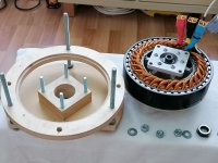
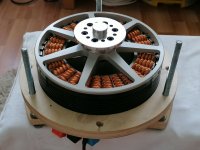
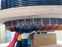
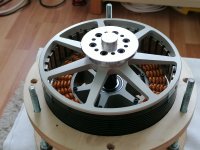
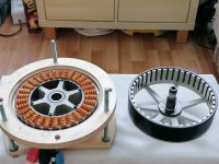
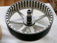
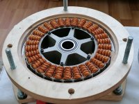
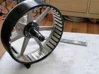
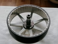
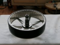
The motor was made by scaling up a smaller motor, (was still 20pp and 30 teeth but only 10kw), i did calculations for the winding, i drew it in 2D cad, went to a machine shop and told them what parts i need, the stator laminations were laser cut (unfortunatly 0,5mm thick), then a full day of winding. It was not even by far such complex to make as the ESC.
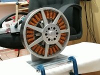
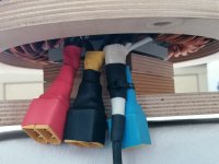
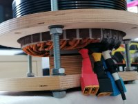
It's mass is 7.7kg, 216mm OD, 40mm stator hight, 40x10x5 N45 magnets, 6mohm and 10uH per phase, delta terminated, 3 halls and 1 temp sensors. It can do 16Kw continuous and 22Kw max (1 min) at 20 deg C ambient, being air cooled ambient temp affects max power.
And here are some photos of the system.
View attachment 305035
View attachment 305036
View attachment 305037
View attachment 305038
View attachment 305039
View attachment 305040
View attachment 305041
View attachment 305042
View attachment 305043
View attachment 305044
View attachment 305045
View attachment 305046
View attachment 305047
View attachment 305048
View attachment 305049
View attachment 305050
View attachment 305051
And in the present the 7-th year V1.3 (IRF150P220 FET-s) gives headakes as mention in my other post (300A ESC help...). The change (FET-s) was made in order to go with 22s battery.
It looks like this, with PCB-s made by specialized company, power board has 1mm thick water jet cut busbars.
View attachment 305052
View attachment 305053
View attachment 305054
This is just a short story, the hole experience has waaaaaay more detalis and waaaay more headakes.
There is a lots of room for improvement, this is very low tech, and to some may be even foolish, i know, up to this point it was the best i could do, but will see what future shows up.
Amazing ! On your first few picture i see you are using MC33035 and later on looks different chip ? I'm also working on sensored bldc controller. Do you recommend MC33035 or something else ?Hy guys, i will move here the discussion about my 20Kw motor and 300A esc. This is been a project for my past 6 years, it's been a huge learning curve. Before i started this project my experience with electronics was with power audio circuits, analog stuff, and nothing digital.
I will start first with the electronic speed controller because that took most of the time to learn and develop.
So i begun with a BLDC monolithic driver chip, the MC33035, and i made the circuit with wires, it took me a month to get it running and be able top spin a small BLDC sensored motor, it looked like this:
View attachment 305026
It was capable of about 12w ,24v at 0.5A, then i learned what MOSFET stands for: Magically Obliterated, Smoke and Fire Emitting Transistor, i was amazed how much smoke can make a TO220 packge, inductance was my friend (bundle of wires), but at that time i was blissfully unaware of it. Then i learned a few things and moved the project to PCB, i was so impressed about my first toner transfer technique PCB, but from electrical stand point was crap, again i did not know that, this is how it looked,
View attachment 305028
This was the first year and it was capable of about 48w ,24v at 2A, before it wood magically let the smoke out of the FET-s, at that level i learned about that thing called "ringing"....Then i learned a lot more things, i added a few functionalities like safestart, rpm, voltage, current and tep readout, all made on 4 digit 7 segment display, it was a lot of work, and it looked like this, (the big motor was made at this point) ,
View attachment 305029
This was the second year it was capable of about 120w , 36v at 3.3A, o about that time i realized i need to move up a bit and enter the AVR microcontroller world, i knew nothing about them, and all i knew about C programming language was that there was some things called "if" and "else"..., then another year of huge learning curve and another variant of the controller came witch was way easier to customize and change things, hence programmable microcontroller, it looked like this
View attachment 305030
This was in the third year became V1.0 it is capable about 2.5kw 20S(84v) 30A (current sensor limited),IRFP4468 FET-s , it has BMS and a lot of functionalities including 128x64 GLCD with menu where a lot of parameters can be customized, then the learning curve was the most steep making the ESC to work up to 16kw, then i learned what inductance can really do, and what miller plateou, reverse transfer capacitance, stray inductance, and a lot of goodies that give a lot of headakes...., then came next variantwitch looked like this
View attachment 305031
View attachment 305032
View attachment 305033
This was in the fifth year, v1.2 witch worked up to 16Kw at 20S (84V), IRFP4468 FET-s (6/plase), PCB-s made by me. It was the first and last time i tested the motor by holding the table just myself...:lol: :lol: , it was exiting seeing my work succeed, but kinda scary because i could barely hold the table, the prop was pulling 78kgf
This was how later tests were made, the motor was strapped by the car, no more worries about flying with the table
View attachment 305034
This was in the 6-th year the flight testing.
The motor was made by scaling up a smaller motor, (was still 20pp and 30 teeth but only 10kw), i did calculations for the winding, i drew it in 2D cad, went to a machine shop and told them what parts i need, the stator laminations were laser cut (unfortunatly 0,5mm thick), then a full day of winding. It was not even by far such complex to make as the ESC.
It's mass is 7.7kg, 216mm OD, 40mm stator hight, 40x10x5 N45 magnets, 6mohm and 10uH per phase, delta terminated, 3 halls and 1 temp sensors. It can do 16Kw continuous and 22Kw max (1 min) at 20 deg C ambient, being air cooled ambient temp affects max power.
And here are some photos of the system.
View attachment 305035
View attachment 305036
View attachment 305037
View attachment 305038
View attachment 305039
View attachment 305040
View attachment 305041
View attachment 305042
View attachment 305043
View attachment 305044
View attachment 305045
View attachment 305046
View attachment 305047
View attachment 305048
View attachment 305049
View attachment 305050
View attachment 305051
And in the present the 7-th year V1.3 (IRF150P220 FET-s) gives headakes as mention in my other post (300A ESC help...). The change (FET-s) was made in order to go with 22s battery.
It looks like this, with PCB-s made by specialized company, power board has 1mm thick water jet cut busbars.
View attachment 305052
View attachment 305053
View attachment 305054
This is just a short story, the hole experience has waaaaaay more detalis and waaaay more headakes.
There is a lots of room for improvement, this is very low tech, and to some may be even foolish, i know, up to this point it was the best i could do, but will see what future shows up.
No, (mc33035 is an ASIC), go with microcontrollers, a 32bit one, you will have waaay more flexibility and options. For start, you can go with an 8bit AVR (328) to get things going, then upgrade to 32bit (STM32).Amazing ! On your first few picture i see you are using MC33035 and later on looks different chip ? I'm also working on sensored bldc controller. Do you recommend MC33035 or something else ?
Hy, thanks for you reply, it's been a lot of time since my last post.Congratulations! Always great stuff.
Ideas... Just ideas for the emi and radio interference. I do a lot of this for work, and honestly, having a test center with 100kusd of equipment helps a lot... But you can still replicate the problem and try things so...
I'm presuming you're using AM on the 12xMHz bands? I recall you have ringing at 60 ish MHz which almost certainly has harmonics at 2x that frequency. That ringing is probably being modulated at the commutation frequency. You have a few angles of attack... Eliminate the carrier or eliminate the modulation or eliminate the coupling.
1) the carrier frequency can be attenuated potentially with ferrites, like the clamp ones you sometimes get on per supply cables. Try putting them around the input and output cables to the controller. Try common mode (one on all 3 cables for the motor and the battery pair) and one on each cable.
2) the modulation probably comes from the commutation rate... You could try various things, tunning your pids out changing the advance angle to avoid current spikes, or perhaps move to sinusoidal or even Field oriented control.
3) the wavelength at 120MHz is about 2.5 meters, so theoretically the aerial is fairly long (quarter wavelength is 67.5cm) so it's likely the cables transmitting, though it could be a dipole antenna from your PCB.
4) try grounding to your frame at many points or completely isolate it.
5) controller in a big metal box with ferrites on the exits
6) I presume you've got the radio powered from a separate power source? And that is isolated from the frame etc? Conductive coupling is usually far stronger.
7)Test to see if it's the battery cables by adding extra bus capacitance and seeing if the interference changes. You could also try adding extra FET output capacitance, perhaps you can change the ringing frequency?
8) Completely screening the cables with copper tape can help but you need to eliminate all gaps. Depending on the nature of the emission source the copper tape can just radiate equally.
Usually, most things will make barely any difference and one thing makes a huge difference. Good luck
Congratulations on the job situation! Somehow I'm still doing mechanical engineering for robotics not electronics but it's all good work so hey!Hy, thanks for you reply, it's been a lot of time since my last post.
A lot has happened, one of the main things is that this project got me a JOB in electronics industry, big career change for me.
Anyway, here it goes.
I di try shieling the phase cables, unnoticeable effect.
I did put ferrite beads on every cable that goes in and out of the controller, a bit of improvement ,enough for the interference not to open the squelch at max.
Antenna grounded or isolated no effect.
Radio is own battery powered.
Controller is in a metal box well grounded
Did change the PWM SW freq up to 24khz, little effect.
All in all, moving the antenna in the tail and ferrite beads on cables had improvement.
My next approach is to try to slow down my rise/fall time for turn on/off , and tune a bit the snubbers to eliminate the ringing.
Also on my list is to migrate from 8bit AVR's to STM32, and try different controlling modes, like FOC, because at this time it is clear that the current ripple that i have is mainly part of the cause of the interference.
At this time, i'm dealing with a phase damage, it got fried at very low load (when reducing power after a runup on the ground), basically the controller worked for about 2,5 hours in total time with no functionality problems. Upon investigation i found cracked and and shorted ceramic caps (the ones on the rails between fet-s) on the damaged phase, and one completely blown ceramic cap on a good phase, I have reasons to believe that they ware stressed by to much ripple, they ware flex terminated 4,7uF 100V mlcc, so mechanical stress is out of the question, this also proves that i have to much current ripple in the controller.
If you have any thoughts with regard to mlcc failing due to current/voltage ripple.
I have a dev board with a stm32f4, i made a few tests with ADC , timers, some filtering with floating point math, and i'm blown about it's computational power compared to 8bit AVR's.Congratulations on the job situation! Somehow I'm still doing mechanical engineering for robotics not electronics but it's all good work so hey!
I've not seen mlcc crack from ripple or even get hot yet but iirc you were running way way up at their max voltage and generating a huge amount of ripple. Try putting 2 in series. You'll find that due to the way they derate with voltage you don't lose much capacitance.
Then go to FOC as soon as you can. If it's an option, put an abi encoder on your motor. I wired one into my controller a week ago and it blew my mind how easy it was to interface and get perfect angle measurement from it. With an encoder working, FOC is barely a few evenings work to implement on stm32. Don't bother with the lower end simple ones, go straight to f4 with triple ADC or H7, and try to get one of the ones with higher clock rate. Ignore G4, they have a serious ADC errata.
If you stuck with BLDC, try counting the pwm periods per hall segment and either implement a phase advance or just roll back the duty on the last few pwm pulses to avoid the current spikes (they normally happen at the end of the commutation phase).
Normally when things like this happen, it just means you did not realise you dropped a screw on it or added some code that commanded a shoot through or whatever. It's pretty unlikely that you blow through a completely separate unconnected phase, unless it was not even connected to the gate drivers/MCU left floating/... something that would allow the gates to turn on.I'm back with a bit of trouble,
i made some DPT in order to fine tune the desat overcurrent protection on each phase, i found this [FAQ] UCC21750: How can we adjust the DESAT detection threshold in UCC217xx & ISO5x5x? - Power management forum - Power management - TI E2E support forums
it helped me to better understand the adjustment.
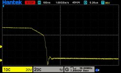
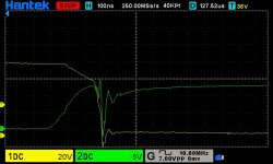
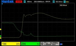
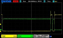
Now the problem, i was testing desat on phase W low side and phase V high side with an inductor (one phase of the motor connected) between them, i was giving 100us pulse for 450A DPT. At some point due to my mistake the microcontroller commanded 4 long pulses (certainly longer than 100us) in a row, witch damaged the power stage, it fried phase U witch strangely enough, was not connected to any load (it's switching node was not connected to any thing) , phase W had desat set up, i suspect that saved it. But what could kill phase U, witch was not commanded to do anything and not connected to any load, could the spike generated by the DPT on other phases (W and V) transfer thru to phase U. I thought that the phases involved in the test would get fried, but not. This is baffling, also adds to confusion that phase W got fried last time when throttling down the motor from high load to light load (10kw to under 1Kw) at light load it got fried. Gate driver checks out fine for phase U, it behaves and measures as other phases (except desat).
So any thoughts on this might be helpful .
Thanks in advance.
With regard to resistors, they are there from the beginning of this version, but what i want is to change they're value from 1r to 2.2/3.3/4.7r, and see what changes. Strange enough is that capacitors 4,7n or 10n in parallel with the gates made things worst....... but I do understand the reasoning and now fit the extra resistors.
......
I'm very sceptical that this caused your failure though, you double pulse tested to over 1kA and it failed when that leg wasn't even being used? This seems very unlikely.
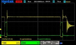
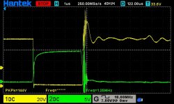

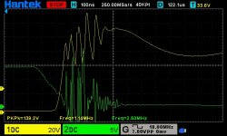
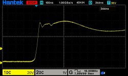

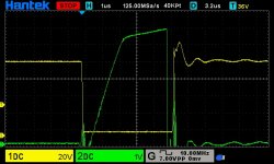
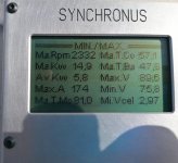
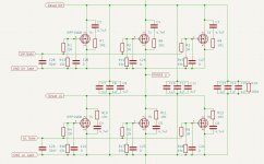
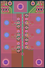
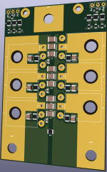

The 1uF mlcc on DC bus, i see them as them as HF decoupling on DC bus, and good to have there, although when going from 9pcs 4,7uF to 9pcs 1uF i did not see any big difference on the waveforms, and probably they do not do much, since there are RC snubbers on each mosfet. They are flex terminated mlcc.What is the thought process of those 1uF ceramic caps on the DC bus? Notice any difference with them vs without them? I tried something similar, but with polypropylene caps as large ceramics are prone to cracking under thermal stress + suffer dielectric effect. I don't recall seeing any notable differences when I played with it.
Looks like your gate traces are running through you power pass section, this is generally considered a bad idea at higher power levels due to coupling. Twisted pair flying leads could be a work around, however with the vibration issues for your application it may not be a good idea unless you they are mechanically secure and vibration isolated.
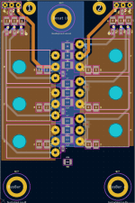
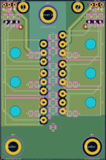
Wow. I might eventually need 20kw + motors for a full sized version of an experimental aircraft: Login • InstagramHy guys, i will move here the discussion about my 20Kw motor and 300A esc. This is been a project for my past 6 years, it's been a huge learning curve. Before i started this project my experience with electronics was with power audio circuits, analog stuff, and nothing digital.
I will start first with the electronic speed controller because that took most of the time to learn and develop.
So i begun with a BLDC monolithic driver chip, the MC33035, and i made the circuit with wires, it took me a month to get it running and be able top spin a small BLDC sensored motor, it looked like this:
View attachment 305026
It was capable of about 12w ,24v at 0.5A, then i learned what MOSFET stands for: Magically Obliterated, Smoke and Fire Emitting Transistor, i was amazed how much smoke can make a TO220 packge, inductance was my friend (bundle of wires), but at that time i was blissfully unaware of it. Then i learned a few things and moved the project to PCB, i was so impressed about my first toner transfer technique PCB, but from electrical stand point was crap, again i did not know that, this is how it looked,
View attachment 305028
This was the first year and it was capable of about 48w ,24v at 2A, before it wood magically let the smoke out of the FET-s, at that level i learned about that thing called "ringing"....Then i learned a lot more things, i added a few functionalities like safestart, rpm, voltage, current and tep readout, all made on 4 digit 7 segment display, it was a lot of work, and it looked like this, (the big motor was made at this point) ,
View attachment 305029
This was the second year it was capable of about 120w , 36v at 3.3A, o about that time i realized i need to move up a bit and enter the AVR microcontroller world, i knew nothing about them, and all i knew about C programming language was that there was some things called "if" and "else"..., then another year of huge learning curve and another variant of the controller came witch was way easier to customize and change things, hence programmable microcontroller, it looked like this
View attachment 305030
This was in the third year became V1.0 it is capable about 2.5kw 20S(84v) 30A (current sensor limited),IRFP4468 FET-s , it has BMS and a lot of functionalities including 128x64 GLCD with menu where a lot of parameters can be customized, then the learning curve was the most steep making the ESC to work up to 16kw, then i learned what inductance can really do, and what miller plateou, reverse transfer capacitance, stray inductance, and a lot of goodies that give a lot of headakes...., then came next variantwitch looked like this
View attachment 305031
View attachment 305032
View attachment 305033
This was in the fifth year, v1.2 witch worked up to 16Kw at 20S (84V), IRFP4468 FET-s (6/plase), PCB-s made by me. It was the first and last time i tested the motor by holding the table just myself...:lol: :lol: , it was exiting seeing my work succeed, but kinda scary because i could barely hold the table, the prop was pulling 78kgf
This was how later tests were made, the motor was strapped by the car, no more worries about flying with the table
View attachment 305034
This was in the 6-th year the flight testing.
The motor was made by scaling up a smaller motor, (was still 20pp and 30 teeth but only 10kw), i did calculations for the winding, i drew it in 2D cad, went to a machine shop and told them what parts i need, the stator laminations were laser cut (unfortunatly 0,5mm thick), then a full day of winding. It was not even by far such complex to make as the ESC.
It's mass is 7.7kg, 216mm OD, 40mm stator hight, 40x10x5 N45 magnets, 6mohm and 10uH per phase, delta terminated, 3 halls and 1 temp sensors. It can do 16Kw continuous and 22Kw max (1 min) at 20 deg C ambient, being air cooled ambient temp affects max power.
And here are some photos of the system.
View attachment 305035
View attachment 305036
View attachment 305037
View attachment 305038
View attachment 305039
View attachment 305040
View attachment 305041
View attachment 305042
View attachment 305043
View attachment 305044
View attachment 305045
View attachment 305046
View attachment 305047
View attachment 305048
View attachment 305049
View attachment 305050
View attachment 305051
And in the present the 7-th year V1.3 (IRF150P220 FET-s) gives headakes as mention in my other post (300A ESC help...). The change (FET-s) was made in order to go with 22s battery.
It looks like this, with PCB-s made by specialized company, power board has 1mm thick water jet cut busbars.
View attachment 305052
View attachment 305053
View attachment 305054
This is just a short story, the hole experience has waaaaaay more detalis and waaaay more headakes.
There is a lots of room for improvement, this is very low tech, and to some may be even foolish, i know, up to this point it was the best i could do, but will see what future shows up.
Finding an off the shelf for these high power motors for a specific application is not very common, they might be a partial match, but that is not ideal. For specific application you need the motor to be made to match you requirements. Electric propulsion in aviation is not very common yet, so off the shelf electric motors for typical applications are not here yet, like ICE counter parts have rotax582 or 912, etc. . There are a few manufactures that make these high power motors and have a customizable rage of specs, although they are kind of pricy. I made an assessment in order to produce my motor (better updated version) to be sold as one of from time to time and it will be around 2800 euros, or 2 pieces at once is about 2200/piece , and so on. So one of is the worst case, that is why off the shelf is not very common, no one keeps this things "on the shelf" to sell them rarely because they cost a lot. China does it, but there variety is not very broad, quality and specs are ambiguous, generally specs are over rated by a factor of 2 or 3, plus they are not very cheap either. So on that note, it can be done, but a price must be payed.Wow. I might eventually need 20kw + motors for a full sized version of an experimental aircraft: Login • Instagram
I had assumed that would use off the shelf motors, but maybe you could make custom motors to match my 5-bladed variable-pitch rotors if it turns out that a good match is hard to find ?
Of course this is many years away, but it seems a long running project hasn’t fazed you!
Thanks a lot for that advice!Finding an off the shelf for these high power motors for a specific application is not very common, they might be a partial match, but that is not ideal. For specific application you need the motor to be made to match you requirements. Electric propulsion in aviation is not very common yet, so off the shelf electric motors for typical applications are not here yet, like ICE counter parts have rotax582 or 912, etc. . There are a few manufactures that make these high power motors and have a customizable rage of specs, although they are kind of pricy. I made an assessment in order to produce my motor (better updated version) to be sold as one of from time to time and it will be around 2800 euros, or 2 pieces at once is about 2200/piece , and so on. So one of is the worst case, that is why off the shelf is not very common, no one keeps this things "on the shelf" to sell them rarely because they cost a lot. China does it, but there variety is not very broad, quality and specs are ambiguous, generally specs are over rated by a factor of 2 or 3, plus they are not very cheap either. So on that note, it can be done, but a price must be payed.
unrelated question ,. you always emphasize on the idea of traces running through power section and routing gate/return in differential pair or kelvin connection i donot remember .What is the thought process of those 1uF ceramic caps on the DC bus? Notice any difference with them vs without them? I tried something similar, but with polypropylene caps as large ceramics are prone to cracking under thermal stress + suffer dielectric effect. I don't recall seeing any notable differences when I played with it.
Looks like your gate traces are running through you power pass section, this is generally considered a bad idea at higher power levels due to coupling. Twisted pair flying leads could be a work around, however with the vibration issues for your application it may not be a good idea unless you they are mechanically secure and vibration isolated.

 endless-sphere.com
