20Kw motor and 300A ESC (ultralight aircraft propulsion system)

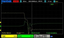
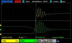
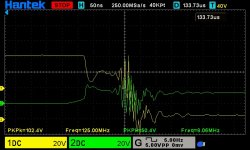
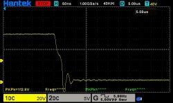
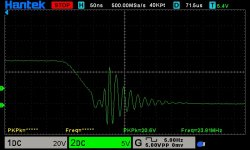
On the way to work, it came to me why so much ringing after miller clamp kicks in, well that 10mm gnd lead forms a loop with the probe tip after the gate si shorted to source by the miller clamp, and then all that ringing is picked up inductive by that 10mm loop of the probe gnd to tip from the negative bus plate, hence ringing being centerd with respect to gnd (on Vgs trace after turn off)
And that is also why at low current there was no ringing at turn off Vgs, there was nothing to pickup.
The Vds the ringing is much smaller then Vgs, becuse the gnd lead of the other probe is much more shorter...
Bummer, i bashed my head around all weekend, trying to sort it out.. :oops:
 
It might be worth soldering twisted pairs to the MOSFET drain source and gate source and connecting the scope a few cm away from the board. That should minimise your probing inductive pick up. Also less chance of the kind of short that obliterates your probes...

I had to do that with my 2 board controller. Was hopeless/dangerous doing it with just the springs.

Re. The fets... Like I said, it's futile trying to switch these FETs slowly. They are optimised to be on or off with no in-between. Infineon have gone to great lengths to ensure this is the case.

To switch slowly, you need the miller capacitance since it provides a negative feedback. You then use resistors, external capacitors... To control the oscillations that result from this feedback.

The more modern FETs do not work with that mechanism. All you can do is eliminate all the parasitic inductance and provide good decoupling so that the overshoot is minimised, and snubbers to eliminate any persistent ringing.

Why have they done this? Efficiency. Switching losses are losses and progress dictates that we eliminate them.

The output capacitance of the more modern FETs tends to be higher which also helps with the rapid switching. Also the ruggedness to avalanche is documented and controlled.
 
i'm back with more tests, same 1ohm Rg, i did solder twisted pairs routed them away from bus plates and probe on to those, same result as before when probing on fets legs close to bus plate (440A test)
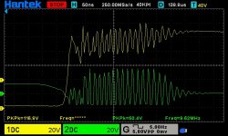
here are a few shots that show the same amplitude of ringing on both Vds and Vgs, witch makes me think it might be source inductance (wire bond inside fet) ringing...
dso_01_01_00_51_53.jpg
dso_01_01_00_52_40.jpg

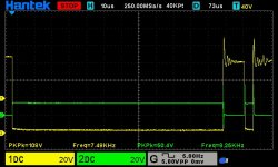
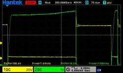
and then i decided to go up to 1000A, so i did a 120us pulse witch gave 1030A, not that bad considering it switched off that current in 25ns, so here are the shots
dso_01_01_01_22_20.jpg
dso_01_01_01_17_15.jpg
dso_01_01_01_18_13.jpg
dso_01_01_01_20_26.jpg

so with this test, i think is ok to proceed to more continous currents, like runing the motor under load (with the prop)...
desat still did not trigger, but now i'l start investigate that to.
 
I'm back, i set up the desat, after a lot of tries, i managed to get it right, it tripped after 88us at 760A, i used 2 zenners in series 5v1 and 2v4 to get it right, and the funny part is that with 7v5 din not work right, it triggered after 5ish us.
My aim was somewere between 750A and 800A to trigger desat.
Now, i do not quite feel like doing a shut thru test yet, i'l try first a short at the controller phase leads, but still i am a bit afraid, because it is contra intuitive to short out on purpose your controller... :shock: , i did not ever tried such ting yet, but it is like the 1000A pulse test, at the first one i was nervous, but now after a day of a lot of 1000A pulses (at some point it hit 1200A), it feels normal :mrgreen:
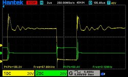
So here is the shot of the desat triggering, yellow Vds, green is desat voltage, the long pulse was programed at 120us the 5us pause then another 5us pulse, the usual DPT i used on all thests, and you can see the long pulse ended at 88us desat triggered.
dso_01_01_01_31_17.jpg
 
Good going.

I used to think 200A was a lot but after a VESC I built survived a series of 600+amp errors (eventually the dcdc died) I no longer feel so concerned.

1200 is an awfully large number of amps though :lol:

I'm hoping zombiess chimes in to explain why the miller clamp seems to trigger more ringing than anything else.

Tbh it's strange to me that you seem to get more ringing with this new big complicated isolated driver than the old cheap single chip one.

If you create a shoot through, there's no guarantee your desat will catch it. You've devoted a lot of effort to massively minimising the inductance of your stage, the effective load from you caps V+ to ground is like... A few nano henries. The only significant impedance is the capacitors impedance themselves and the battery wires.
 
How is the shielding between the copper bars and the pc boards above them? What about shielding for traces / connections on the fet boards?
Do you have something that shields emi well that you can safely put in between and retest to see if it makes any difference?
I've seen some designs turn the driver board 90° to the fet board. I think this is to help keep emi out of the driver boards when dealing with large power levels.

I've seen companies use 3 antennas with fast logging to triangulate the path of emi so they can try to better understand what's going on. I haven't seen any homebrew version's of this yet.
 
Jrbe said:
How is the shielding between the copper bars and the pc boards above them? What about shielding for traces / connections on the fet boards?
Do you have something that shields emi well that you can safely put in between and retest to see if it makes any difference?
I've seen some designs turn the driver board 90° to the fet board. I think this is to help keep emi out of the driver boards when dealing with large power levels.

I've seen companies use 3 antennas with fast logging to triangulate the path of emi so they can try to better understand what's going on. I haven't seen any homebrew version's of this yet.

The previous version had a 0.1mm sheet of copper between power section and command board, connected to Gnd, that version had only 2 layer boards, and phase cables passed very close between boards, so that shield was needed to improve a bit on the glitches on the analog signals (temp sensors).
This version uses 4 layer boards with Gnd and V+ plains, and power board has a Gnd shield between witching node and bus bars, and boards are at greater distance apart from switchin currents, so will be superior in shielding terms to previous version, but if tests show that the copper sheet shield is needed, i'l put one in this version too. The HW has tons of decupling and filteting, and SW also has a lot of signal filtering and deciding that enything that comes in is valid or not (especially the hall for motor position) . And that is about it in terms of shielding internally.
 
I'm back, with a new test, i did a pwm pulse, 2us on 61us off, for about a second, witch had an RMS current of about 280A (about what the motor will pull at max power) , the purpose of this test was to see if the ringing on the fet gates will hurt them , and all was fine after 16000ish pulses (63us periods in 1sec), i believe if that ringing amplitude in those shots (51v pk-pk) was real, the gates would have blown. The ringing is there for shure, but the amplitude i don't think us real, so my question to you guys, have you experinenced such case of ringing after turn off when Vgs is 0 and miller clamp on, with new fast fets? I'm about to put the prop on and go WOT, and that ringing concerns me a bit, every thing else seems to be ok, all the test show it should work fine.
 
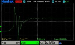
I'm back with some good results. I had a theory about that Vgs ringing being caused by the source stray inductance (wire bond) and Ciss and 1R Gate paralleling resistors and active miller clamp being on (gate shorted to source), all these form an LCR oscillator (basicaly 3 oscillators in parallel, 3 fet-s), so the source stray inductance is energized by the fet turning off at high current and that starts the oscillation. So after a lot of reading and head bashing, i decided to put my theory to test, so i removed the active miller clamp, and guess what, almost all that nasty (51v pk-pk) ringing went away, and also the Vds ringing is way smaller and shorter.
The turn on gate resistor is 1R, this gave the best results at turn on, and the Turn off is 2R2.

The 180degree out of phase Vgs and Vds turn off ringing (see older post shots) supports my theory because as Vgs increases Vds goes down as fet turns on partialy.

So i truly believe that my theory stays true.

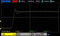
So here are some 440A DPT shots , green Vgs, yellow Vds
dso_01_01_00_15_25.jpg
dso_01_01_01_03_13.jpg
dso_01_01_00_57_49.jpg
dso_01_01_01_03_55.jpg

Now at turn on, that positive and negative pulse on Vgs right when Fet turns on, my theory is: there is a capacitive divider formed by the Ciss and Coss and the midle connection is made by source stary inductance, so as Vds goes down that discharges Coss and forces some charge in Ciss hence that positive pulse that is in perfect 180degree out of phase on Vgs with Vds (see older posts shots), that charge is forced from Coss to Ciss becouse of the source stray inductance witch can't hold Gnd potential, after the Vds reaches 0V it under shoots and that under shoot can be see also on Vgs, same amplitude and phase.
So the conclusion is that the source stray inductance creates all this problems, witch are kinda tricky to mitigate.
 
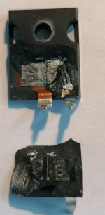
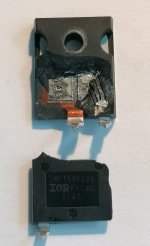
I remenberd that i have a blown IRF150P220 from the past :flame: :flame: experiences, witch has a splitted case and you can see that it has 4 bond wires, they ware made from aluminum, but now are splashed. From the size of they'r location i calculated that it has around 1.2nH inductance in the bond wire alone, and then another 1.1nH the 6mm long leg in my power boards, so the total stray source inductance per device is about 2.3nH. And at 50ns switching time and 150A per device, it has about 7v across that inductance, witch kinda confirms my theory at turn on with the positive and negative pulse on Vgs.

Any way i thought it might be interesting to show this to you guys.

Here are the photos.

IMG_20220527_150630.jpg
IMG_20220527_150539.jpg

Now, i removed all active miller clamps, i don't quit like that they can not be used, but they for sure do more harm then good in my case, and after all this testing and the new results, i feel a bit more confident that i can move forward with testing under full load.

PS. on future plans i will sure like to try some fet-s with Kelvin source sense, like a 4 lead TO247, that way you eliminate all that stray inductance from gate drive circuit, and all the problems associated with it....
 
Great news and thanks for so much information and such an informative thread.

Consider infineon 2EDF8275F if you revise the driver board.

Don't lament the loss of the miller clamp, those MOSFETs need then as much as a fish needs a bicycle.

You might find part of your problem is related to such a large pcb and isolated section flailing up and down with the switch node. The isolated section really wants to be as small as possible and with as little stray capacitance possible.
 
mxlemming said:
Great news and thanks for so much information and such an informative thread.

Well, this forum was a big big source of knowledge, and i found here a lot of useful information, so if i can make something that others might also find useful, why not, because i know how happy i was when i found this forum.
Just a little side note, a few weeks ago, there was an technical university exhibition of electric vehicles "made by the students" and went to the guy (teacher) that presented the exhibition and asked if they built the motors and speed controllers, and they said they bought them, then i asked would you know or does someone in the university know how to make such things, and he said, "no, we just teach basic working principles, such high power (30kw) is beyond our knowledge", then i remained speechless, becouse electronics techinical university in our country is very respectful, and if they don't know then who does... Or maybe my expectations from university are not realistic...
 
Mihai_F said:
Just a little side note, a few weeks ago, there was an technical university exhibition of electric vehicles "made by the students" and went to the guy (teacher) that presented the exhibition and asked if they built the motors and speed controllers, and they said they bought them, then i asked would you know or does someone in the university know how to make such things, and he said, "no, we just teach basic working principles, such high power (30kw) is beyond our knowledge", then i remained speechless, becouse electronics techinical university in our country is very respectful, and if they don't know then who does... Or maybe my expectations from university are not realistic...
I've had similar experiences to you in various fields. I took one of my university professors, who had written many papers around my first work... Directly related to his work... And he was amazed, seemed completely unaware of the scale we were making these 3-5 semiconductor machines. Was really nice to be able to show him how far his work had gone actually...
I've also found universities and industry alike are terrified of motor drives. The company I'm working for now make so kinds of automation machinery and I can say for certain I know by far the most about motor drives of anyone in the building... Which is weird to me. And I actually don't get much involved atall in the software and electronics.

There's certainly plenty of people who have made it their business to understand it very well, and big companies who rely on the technology heavily (cars, industrial automation...) Have departments and well controlled code bases and proven designs. And a lot of outsourcing...

I think it's just a niche that's sufficiently complex that you have to really immerse yourself and be obsessed with to understand.
 
IT WORKS!!! I went out with the table :lol: did some full throttle testing, man i missed the sound of 3 blades at 2400 RPM and sitting 40cm behind it :p . It pulled 182A (battery amps) 16kw, the battery was not fully charged.

The test was done to simulate a short flight, 60 sec full throttle for take off, then 2 minutes 12Kw, then 10 minutes 7 Kw, a short flight around traffic pattern. Outside temp 26degC and pressure 979hectopascals. After 60 sec 16Kw motor temp got to 51degC, then after another 2 min at 12Kw it got to 59degC, the controller got up to 39degC after those 3 minutes, the battery got up to 46degC, then for the rest of 10 min motor and controller them went down slowly, but batt temp stayed at 46 till the end of test. I expect these temps to be a little lower in the air because of better airflow mainly over motor, in this static test motor does not get enough airflow from prop.

The conclusion after a 13 minute test: the controller works ok (it needs a few software tweaks here and there), motor and prop rock's, the battery on the other hand it is a bit old and it's internal rezistence went up a bit with time, at the start of test it had 91V and in the first seconds after applying full power it went down to 86V, that is 5V drop for 16kw, it does not sound much but is almost 1Kw of power disipated as heat inside the battery, luckily it has 33kg mass of thermal inertia, so by the time i'm at traffic pattern altitude in 3 minutes i'm done pulling max power, and then it settles slowly the temp rise. Heat management in the battery is critical, controller keeps an eye on that and reduces power when it goes over 55degC, so i'l keep an eye on that. All 22 cells are monitored they all stayed at the same voltage +/- 0,03V, a good sign that all cells aged the same, (each cell consist of 12 parallel cells witch reduces the chances of one cell going bad).

The 4 layer boards and isolated gate drives in the controller are awesome, there ware no interferences from power section to command board, every displayed parameter is still and woks as it should, there ware no abnormalities, it has a log that logs every thing min/max and out of normal... . I could not be happier with how it worked.

I did pull a few agresive throttle up-s, the system took it just fine, but after a few tries i was not confortable any more with the table test stand for such agresion, the motor mount was bolted to the table and tied with straps by the car, but still with such agresion it seemed it might what to pull itself off from the table :oops: , 16kw is no joke :mrgreen: .

The next test will be with the system mounted on the aircraft, a 30 minute static test, in the next days.
 
Mihai_F said:
IT WORKS!!! I went out with the table :lol: did some full throttle testing, man i missed the sound of 3 blades at 2400 RPM and sitting 40cm behind it :p . It pulled 182A (battery amps) 16kw, the battery was not fully charged.
...

Please post videos! Well done, awesome.
 
here is a short video made with the phone, it almost blew the phone out of my hand, hence the shake at the end...
https://youtu.be/I-TUg_LWWjQ
 
Congratulations on the tremendous motor running success!! Woot!!
 
I'm back, I flew it, all was ok. https://youtu.be/ZRt83h8VuNk
I'l be back with details.
 
Mihai_F said:
I'm back, I flew it, all was ok. https://youtu.be/ZRt83h8VuNk
I'l be back with details.

That's just awesome. Massive respect.
 
Congratulations to your massive achievement my friend!! Wooot!!
 
Thank everyone for your appreciation and advice!
The flight went well, it was a traffic pattern flight, the altitude gain was 384ft, max climb rate was 510ft/min, at 17Kw max power.
Now as i said the battery has 6 years, an has aged quite a bit, it's internal resistance has gone up, and that does not allow me to pull more than 17Kw, and after about 30 seconds it drops to 14kw. It can do 12kw for a few minutes with no problem, but max power continous use is limited to 30 sec unfortunately.
That is not that bad becouse after the discarge and charge cycle it still has about 50Ah capacity, when it was new the stated capacity was 60Ah, and that means i can still get about 40min of flight endurance.
One more issue that i anticipated is radio interference, my hand-held radio (FTA450) went buzzing, after i got over 25% power, the squelch was set at 90%, te buzzing was louder that the actual conversations on the radio. I remember that in some ground tests if i moved the radio furder (2m) from the propulsion system, the buzzing went away. I was using the short stock helical antenna, but i believe if i use a 1/4 wave or dipole antenna and mount it on the tail, furder away from the "aggressor", this interference, might decrease its intensity to acceptable levels. On the flight school plane, piston powered, the squelch is at 40%, and antenna mounted on the tail, and it works well.
So that was it, i still have to adjust some parameters on the controller, try different PWM frequencyes, i can go 10 12 14 16 18 20khz, and se witch gives best results, motor advance timing, i'l try different degrees.
I'l report back frequently.
 
nicobie said:
Absolutely beautiful! I am in awe of your skills and admire your bravery flying a home built motor and controller. Did you build the plane too?

:bigthumb: :bigthumb:

Please be careful when in the air. We've recently lost one of our forum geniuses here due to an electric powered ultralight crash.


Just a minor correction. He had many dozens of safe flights when his homebuilt ultralight was electric powered. RIP brother. He passed from an ICE engine sieze 300ft after take off after he converted the airplane to typical rotax 2 stroke ICE power to sell it. He did the recommended break-in procedure and checked all the parts to check and got a clean bill of health on the engine before take off. I miss his amazing contributions in my life everyday.
 
nicobie said:
Absolutely beautiful! I am in awe of your skills and admire your bravery flying a home built motor and controller. Did you build the plane too?

:bigthumb: :bigthumb:

Please be careful when in the air. We've recently lost one of our forum geniuses here due to an electric powered ultralight crash.

Thank you for appreciation.
Condolences for the loss in the community.
About me being brave, well i have to say there are o lot of scenarios that go to my head before take off, but right after applying full power they all go away and the main focus when up there is to fly the airplane, every thing else needs to prioritized, so i apply "PIOSEE" Problem, Information, Options, Select, Execute, Evaluate and then start over. I prepare before take off as best as i can, and make a plan in my head with the flight and with all my options if something goes south, trying to make it muscle memory, so that when it happens, the first reaction is the right one, mainly because some times there is not enough time to think about it before impacting Terra.
Yep, i built the plane to, i started in 2012 and finished it in 2019, then it flew as a glider for one year, then after the electric propulsion was operational it started to fly electric powered.
Also did a wing loading test up to 4gs, i've put 860kg of sandbags on the wings, that was a nerve wrecking test, although i did the math and it should not brake at 5gs, but still... here is a photo
IMG_20210508_173527.jpg
 
Back
Top