20Kw motor and 300A ESC (ultralight aircraft propulsion system)

Hi there,
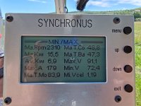
I managed this weekend to get one more flight (30min) out of my battery (21s left), it held 14 to 12kw for 4minutes, then 7kw for almost the rest of the flight. All monitored parameters ware in spec, and about toward the end of flight, all cells reached 3,3v to 3,4v about the same time. Then in about 30 seconds, i could feel the power was fading slowly, a cell (no15 witch was near to no14 that leaked and previously died this year) went almost to 2v, all warnings went on, i overwrite the "safety cutoff" (i knew that the cell is done, no recovery), restarted and then with reduced power turned for a landing (i was in a traffic pattern all the time to be safe and close to the runway), during the last 2 minutes, till on the ground, it wet to 0 volts and stayed 0V even the next day, so completely obliterated. I'l come back with pictures of the yet another dead cell, most probably got corroded like the last one. A note is that at 22s i could get 16Kw max last year, at 21s i got 14kw max this weekend, but from now at 20s, 12kw is not enough for initial climb out, at least not a safe one, at 14kw it felt marginal... I could split the reaming 20s in two 10s banks and use for my ground based projects and squeeze the remaining life out of it.
 
Will you build a new battery pack for this project? If so, what cells will you use?
the cells that would use are made by LG chem lithium NMC/ NCM712,- pouch rectangular, and will be ider individual or from vw id batt module, a pack with about 100 to 120Ah 50 to 64 kg 22 or 24s in order to have about 80-90 min flight time. I found some sources here in europe that have LG chem 51Ah cells, also found vw id modules NCM712 12S 6,85Kw/h , i would prefer the module since it has the structure that holds securely and tight the cells .
I'm not decided yet if to by new battery, everyone suggest to convert it to gas motor, because i'l have way more flight endurance, that sounds very tempting, but then there are some big technical challenges to overcome, plus it feels wrong to go backwards in technology, i mean electric is the way to go not smoky gas guzzling, mixed feelings here, i like the simplicity and smoothens of the electric but i like the range (and power) of gas, for the same amount of money invested...
Some cool things, is that at the airfield every time i fly or take out the plane, there are a many of people that come around to see it and they think is so cool, it has a reputation around there of being what it is, and every time i announce the flight with "Electric Ultralight" to the tower (we have class C airspace there, LRCL international airport near by) the controller pauses for a second to comprehend the "electric" term, so neat.
So, it is etching me bad to by new battery and continue....
 
Hy guys, i will move here the discussion about my 20Kw motor and 300A esc. This is been a project for my past 6 years, it's been a huge learning curve. Before i started this project my experience with electronics was with power audio circuits, analog stuff, and nothing digital.
I will start first with the electronic speed controller because that took most of the time to learn and develop.
So i begun with a BLDC monolithic driver chip, the MC33035, and i made the circuit with wires, it took me a month to get it running and be able top spin a small BLDC sensored motor, it looked like this:
View attachment 305026
It was capable of about 12w ,24v at 0.5A, then i learned what MOSFET stands for: Magically Obliterated, Smoke and Fire Emitting Transistor, i was amazed how much smoke can make a TO220 packge :oops: , inductance was my friend (bundle of wires), but at that time i was blissfully unaware of it. Then i learned a few things and moved the project to PCB, i was so impressed about my first toner transfer technique PCB, but from electrical stand point was crap, again i did not know that, this is how it looked,
View attachment 305028
This was the first year and it was capable of about 48w ,24v at 2A, before it wood magically let the smoke out of the FET-s, at that level i learned about that thing called "ringing"... :oops: .Then i learned a lot more things, i added a few functionalities like safestart, rpm, voltage, current and tep readout, all made on 4 digit 7 segment display, it was a lot of work, and it looked like this, (the big motor was made at this point) ,
View attachment 305029
This was the second year it was capable of about 120w , 36v at 3.3A, o about that time i realized i need to move up a bit and enter the AVR microcontroller world, i knew nothing about them, and all i knew about C programming language was that there was some things called "if" and "else"... :shock: , then another year of huge learning curve and another variant of the controller came witch was way easier to customize and change things, hence programmable microcontroller, it looked like this
View attachment 305030
This was in the third year became V1.0 it is capable about 2.5kw 20S(84v) 30A (current sensor limited),IRFP4468 FET-s , it has BMS and a lot of functionalities including 128x64 GLCD with menu where a lot of parameters can be customized, then the learning curve was the most steep making the ESC to work up to 16kw, then i learned what inductance can really do, and what miller plateou, reverse transfer capacitance, stray inductance, and a lot of goodies that give a lot of headakes.... :shock: , then came next variantwitch looked like this
View attachment 305031
View attachment 305032
View attachment 305033
This was in the fifth year, v1.2 witch worked up to 16Kw at 20S (84V), IRFP4468 FET-s (6/plase), PCB-s made by me. It was the first and last time i tested the motor by holding the table just myself... :shock: :lol: :lol: , it was exiting seeing my work succeed, but kinda scary because i could barely hold the table, the prop was pulling 78kgf :shock:
This was how later tests were made, the motor was strapped by the car, no more worries about flying with the table
View attachment 305034
This was in the 6-th year the flight testing.
The motor was made by scaling up a smaller motor, (was still 20pp and 30 teeth but only 10kw), i did calculations for the winding, i drew it in 2D cad, went to a machine shop and told them what parts i need, the stator laminations were laser cut (unfortunatly 0,5mm thick), then a full day of winding. It was not even by far such complex to make as the ESC.
It's mass is 7.7kg, 216mm OD, 40mm stator hight, 40x10x5 N45 magnets, 6mohm and 10uH per phase, delta terminated, 3 halls and 1 temp sensors. It can do 16Kw continuous and 22Kw max (1 min) at 20 deg C ambient, being air cooled ambient temp affects max power.
And here are some photos of the system.
View attachment 305035
View attachment 305036
View attachment 305037
View attachment 305038
View attachment 305039
View attachment 305040
View attachment 305041
View attachment 305042
View attachment 305043
View attachment 305044
View attachment 305045
View attachment 305046
View attachment 305047
View attachment 305048
View attachment 305049
View attachment 305050
View attachment 305051
And in the present the 7-th year V1.3 (IRF150P220 FET-s) gives headakes as mention in my other post (300A ESC help...). The change (FET-s) was made in order to go with 22s battery.
It looks like this, with PCB-s made by specialized company, power board has 1mm thick water jet cut busbars.
View attachment 305052
View attachment 305053
View attachment 305054
This is just a short story, the hole experience has waaaaaay more detalis and waaaay more headakes.
There is a lots of room for improvement, this is very low tech, and to some may be even foolish, i know, up to this point it was the best i could do, but will see what future shows up.
Yes incredible.
 
Hy there,
I bought 5000mAh hobby king cells to replace the 2 dead cells from the battery. I chose the same cells again, because I have 2 packs 3s and 4s that are 9yrs old (same batch as my ultralight plane batt) and i abused the heck out of them on my rc car and plane the past 3-4 yrs they still charge up to specks, a little puffy but they have the needed punch, so they're quality is quite good.... plus i only had the funds to fix the battery not to buy new battery and in the mean time i could do more flying. These cells i'll wrap and isolate them so that if other leak can not reach inside to them to corrode them...plus i'l check, isolate/replace any leaking cells, i'l apply all lessons learned so far... all in all was/is a good battery but i've made some mistakes with it... i did a test on it ant the rest 20cells work ok, so i'l fix it and continue forward!
Now, the FOC version is on work, the new PCB si nearly ready and the sensorless FOC SW works well for propeller load.
 
After i replaced the dead cells from battery, i charged it up, it took 45Ah, but wasn't completely drained down.
Sunday went flying, did a 30min nice flight, din pull 15.5Kw max power, that is the usual, batt age. The temps got up a bit since was 30degC ambient. Min Vcell still has some bugs in the code it does not record right..., All cells survived, they ware monitored carefully and when first got to 3.0V , reduced power and started the descent. So far so good.
here are some pictures air to air.

IMG-20240616-WA0001v2.jpg
IMG-20240616-WA0002.jpg

IMG_20240616_104117.jpg
 
Great project and beautifully engineered motor and controller.

Have you perhaps considered going series hybrid for longer flights?
ie:
A very small, efficient ICE (normally from motorbikes) with a high efficiency PM alternator/motor that can provide cruise power + a little to charge the batteries. (Or less if you just want X minutes of added flight time)
NB that ICE efficiency goes way up and is way easier if tuned for constant rpm.

There are a number of successful small series hybrid builds on the net, as well as research papers.
They take some finding, but are in my favs somewhere. If you like I'll find them for you.
The VLR Bumblebee comes to mind as a cheap solution: (air cooled and the stock, if rewound, alternator)

I'm thinking a water cooled (way quieter) ~50 to 100cc? engine that exhausts through the frame and way out the back to make it quieter without too much added weight.
This 'frame does double duty as an exhaust muffler' works surprisingly well:
You'd just want to block flow through pipes close to 'melty bits'. It's surprising just how much cooler Quarter Wave Resonator pipes on cars stay. (Youtube)
(You'd definitely want to do that Quarter Wave Resonator maths before deciding which pipes to block where...) ;)

Another option, with your simple curve wing is to try adding solar:
Cells that can do simple curves are available.

There are a couple of videos, with numbers, by the RC guys:

I doubt solar will keep your plane in the air all day (its not very aero) but it might just give you the flight time you desire.
Another nice thing is that the solar weight is on the wing and wont increase your wing loading or mess with CG.

Speaking of aero:
There's quite a lot of 'low hanging fruit' on your plane that can be improved. (flight time)
Teardrop shaped tubing for the wing brace for a start:
Square tube Cd: 2.05​
Round Bar/pipe Cd: ~1.17 (1.75X lower than square)​
Aero teardrop (wing) shape Cd: 0.045 (45.56X lower than square and 26X lower than round)​
That goes all the way down to increasing aero/cooling through the motor and ctlr box.
This is an area on which I can speak and quote white papers etc if you like.


As for the ctlr: I'm damn close to clueless, except maybe for this:
GaN transistors and integrated circuits allow increased power density in electric motor drive applications. Optical layout enables oscillation-free output waveforms and clean current reconstruction signals. EPC presents a reference design for motor control of pedal-assisted bicycle​
 
Logic11

Thanks!
Hybrid applications for land vehicles is not the same as for aircraft, and what i mean by that, is the RPM and speed range and the variations of those. With a land vehicle you start and stop moving and accelerate and decelerate way more frequently (as the road/ traffic imposes), but an aircraft it starts and it goes up to speed where it stays for pretty much (95%) its entire flight, especially an ultralight aircraft. The idea of hybrid system is to use the ICE at its most efficient RPM then use electronics to control the traction motor speed as needed. So for an ultralight aircraft since is it has a defined fixed cruise speed, it is more efficient in terms of weight and simplicity and overall performance to use the ICE to spin the prop (with redrive if needed).

The solar idea is verry tempting, i'v been involved with a solar project lately, and there is great potential to it. A wing full of solar panels on it (18sqm) can deliver a few Kw (2-4), although its implementation is trivial since my wings are fabric covered and also a bit flexible, so yeah... there are flexible solar panels..., but so far did not do anything in that direction...

As regard to making the aircraft more aerodynamic, well at 45Km/h airspeed, the drag is there since is an open cockpit aircraft, there are a few improvements that can be done, but the return benefits do not outweigh the efforts and costs of modifying the airframe....considering it's an recreational aircraft and considering that it already costed me about 15K euro just to make it (without my time invested). So that is that....

The upgrade of the controller is on the waiting list, there will be some major modifications, but for now there are other projects on the work.

Gas hybrid:
Yes the gas-electric hybrid model does not make much sense to me either in aircraft, yet it seems to be quite a widespread phenomenon?
I guess it may have more to do distributing power to multi-prop aircraft?

A quick look points to parallel hybrid being better suited to your application.

Solar:
Fabric covering I haven't done in years! :) Not since hobbies (gliding) were affordable and safe from theft here.
I NB that some RC guys are putting solar UNDER a clear fabric like top covering.
If there is any similar covering available for larger aircraft I cant find it..?

Do you wish to be able to fly 'all day' or just extend flight time by a certain amount?
2 to 4 kw gets one pretty far in today's gliders.

(I like that your rudder is mostly below the tail boom: It means that torque from the rudder assists the ailerons rather than fights against them...That's pretty aero! :) )
 
Back
Top