2WD trike pulling left when accelerating

It sounds like a prominent problem so no doubt he will find the solution.
He will be stoked when he does... And probably learn a ton on the way.

DIY FTW

Looking forward to the solution.

-methods
 
cboy said:
Well, looks like the hub motor is the culprit. I swapped controllers side to side, reran the Angle ID program and took it for a test ride. Pulls hard left, just as before. Anyone have ideas for troubleshooting at this point?
That was a big step forward. Not good, but good sleuthing progress...

A tricky thing about 2WD is that start-up problems by one motor are masked by the other motor getting things rolling. Once rolling a dead hall or phase can be hard to notice - except for a large torque loss - a symptom that you have. That said, it's odd that the controller doesn't complain in the autotune step (halls and winding would seem ok), and the discovered autotune parameters are identical (which suggests the motor Kv -(motor windings) are the same).

(A) I would start by inspecting the hall connectors for broken wires (but still intact insulation) or pins pushed back in the plug shroud. This is the easy one. If okay, then on to phase tests...

(B) The next thing is to check the phases. Try this:

  • With the motor leads unplugged from the controller, use either of these two techniques:
    1. Pair-wise Cogging Comparison:
      • Short together any two phase wires, turn the wheel and note the cogging resistance.
      • Repeat the 'shorted phase wire' tests for the other two combinations and compare the cogging resistance.
        Reduced force for a particular combination indicates an open or shorted winding.
    2. 3:2 Cogging Comparison:
      • Short all three phase leads together and turn the wheel to evaluate cogging force.
      • Disconnect a phase lead and test cogging again.
        If the force is the same and not reduced, then that phase is open or has a short.
      • Reattach the phase wire and repeat the 3-wire vs 2-wire comparison for the remaining two phase leads.

This should tell you if a motor winding is kaput. If not you can move on testing the halls.

(C) Last, go to this page on the Grin site and check out the Hall testing procedure.

Hopefully one of these will reveal the actual failure. (A) or (C) are pretty easy to fix. (B) is a motor replacement episode.
 
methods said:
1) lift and listen... Is either motor louder? (Bad combo)

Difficult test for me to conduct. I have a severe hearing loss in both ears and wear hearing aids to try to assist but sounds are a real problem for me and detecting where they are coming from is even more of a challenge. I do detect some noise when rolling at slow speeds but I can't even tell if it is from the front wheel, a rear wheel or ALL the wheels. Perhaps I can coax my wife to walk along side and give me some hints.

methods said:
2) measure freewheel current and speed on each side by removing one controller at a time.

Not sure I understand the test exactly. In one of the posts above I reported a number of "throttle inputs" and resulting motor speeds taken from the Kelly monitoring program. And they were all virtually identical from one controller to the other. But I'm not sure that is what you mean by "freewheel current" and "speed" or how/where to measure freewheel current and or speed.


methods said:
3) exact same rolling diameters? So rim, tire, inflation?

Identical rims, identical tires and almost the same inflation. But just to satisfy my curiosity I went out and put a tape around the circumference and they were within 1/8".

methods said:
4) dragging brake on one side?

At one point I thought this might be part of the problem since I have brand new disc brakes on the rear and one side was, in fact, rubbing a bit and slowing down that tire. But I pulled that caliper off a few days ago and both wheels now spin the same by hand.

methods said:
same kv on motors? Same cogging feel when hand turning?

Don't quite understand the "kv" question. Second part, the wheels do feel the same when hand turning but I don't have any prior experience to say I get a "cogging" feeling. Also, is the cogging feeling you mention only present when the controllers are on, the controllers are off, or both?
 
teklektik said:
I would start by inspecting the hall connectors for broken wires (but still intact insulation) or pins pushed back in the plug shroud.

They all appear okay unless something is broken closer to the motor inside the protective covering.

teklektik said:
With the motor leads unplugged from the controller...

Sorry for sounding dense but what leads do you mean? The three large phase wires from the wheel? Do I leave the smaller hall signal wires and 5volt hot and ground connected or is all wiring to the wheel disconnected?

teklektik said:
Short together any two phase wires, turn the wheel and note the cogging resistance.

I'm assuming that all power is turned off when doing this test. If so, is the cogging resistance created WITHIN the motor itself as the wheel is turned and the magnets etc come in contact (basically turning the motor into a generator)? I suppose this isn't all that important, I just like to understand what I am doing and why.

While waiting I'll perform the test with ALL wires disconnected and with all power off...that way I shouldn't be able to destroy too much.
 
cboy said:
Sorry for sounding dense but what leads do you mean? The three large phase wires from the wheel? Do I leave the smaller hall signal wires and 5volt hot and ground connected or is all wiring to the wheel disconnected?

The important ones are the big phase leads, but I thought it was easier to just speak generally so everything got unplugged and the motor was completely disconnected from power, etc. That said, the hall connection actually doesn't matter - just turn the controller off if you leave things connected....

cboy said:
I'm assuming that all power is turned off when doing this test. If so, is the cogging resistance created WITHIN the motor itself as the wheel is turned and the magnets etc come in contact (basically turning the motor into a generator)? I suppose this isn't all that important, I just like to understand what I am doing and why.

While waiting I'll perform the test with ALL wires disconnected and with all power off...that way I shouldn't be able to destroy too much.
Yes - you have it exactly. This is making the motor into a generator and good windings when shorted by the phase wires resist motion as lots of current flows making lots of torque. Open windings and shorted windings don't make any juice so the shorted phase wires have no effect and all spins easily (or easier).

  • FWIW: I was trying to be brief, but here's a post that explains the whys and wherefores of testing a motor both with and without a meter and illustrates the test current flow for a couple of common tests.
 
teklektik said:
The next thing is to check the phases.

I ran the two phase tests with all wires detached from motor. In the Pair testing, all three combinations had the same resistance as best I can tell. The "cogs" felt the same in terms of frequency and the stiffness of the wheel seemed the same. In the 3:2 test all three combinations felt the same when one of the three leads was disconnected. The "cogging" was clearly different...when three are connected the bumps or cogs are less noticeable. When one is disconnected from the three, the bumps/cogs are less frequent and each seems more pronounced. But the wheel is a bit easier to turn in all thee cases...but not by a huge amount.

I'm on to read about and then do the Hall testing.
 
Hall Testing

Using the steps shown at the Grin Tech site I'm getting an unexpected result. When I probe the red 5v and black ground pins I get 5.01 volts as expected. But when I probe each of the three Hall sensors I get a zero (or very near zero) reading and when the wheel is turned backward I get a "cog" with a 15 volt reading then one with an 11 volt reading. Then in a couple cogs it is back to zero. The expected reading, according to Grin Tech, is 5 volts. Just to see if this was the problem I probed the sensor wires on the "good" wheel as well. These gave almost identical readings. 5 volts on the red/black and then bouncing between zero and 15 volts as I turned the wheel backwards. So this may, in fact, be a problem but ironically it is the same for both wheels. Is there a logical explanation for these voltages being higher that the incoming voltage.
 
What about the battery side of the controller?

I'm assuming you are running two batteries, one for each side. Are these identical? Can you test for voltage sag on each pack under load?

If one pack is sagging more under load then that could lead to decreased performance on that side. This would cause the bike to turn towards the slower accelerating wheel.

If there is a poor connection between a battery and controller it could also be increasing resistance and voltage drop on that side.
 
lionman said:
I'm assuming you are running two batteries, one for each side.

The controllers and motors run off of one battery pact. There is a 12 volt system on the trike, primarily for lights etc.
 
I would just about guarantee that either:

-- the motors are actually different windings, which would give them different acceleration curves (under the same settings ohterwise). For example, on my trike, my left motor is a 4T (MXUS 4504) and the right is a 3T (MXUS 4503). under the same conditions they accelerate the trike at different rates, and have different maximum speeds.

or


--one motor's wire colors are actually run to different halls or phases inside the motor than the other motor, so the color combo to the controller would need to be different (and somehow the controller's auto-configure isn't working).


To check the first, you'll need a way to check the RPM of each wheel. The controller may be able to do this. If not, you can use the CA's speedo input to monitor any one of the hall signals in each motor, one at a time. It doesn't even really matter if you set the speedo up for the right number of poles; you're just checking to see if the speeds are the same between the two motors.

Then, off ground, throttle up to whatever point you like, as long as you know what it is to make sure it is exactly the same for both motors to compare them. If full throttle is possible safely in the offground test, you can do that.

Then note the speed the CA (or other RPM monitor) shows for the motor under test.

THen move the CA speedo input (or other RPM monitor) to the other motor, and repeat the test.

They should be the same. If they are not, and all controller conditions/etc are identical, then the motors are probably different windings.


To check the second, you can go to the thread titled something like: How to Determine the Wiring For a Brushless Motor, to see a few ways you can test the various phase and hall combinations between motor and controller. At each wire combination change simply throttle up just a little bit, slowly, and see how it reacts, watching the CA's Amps to make sure it doesn't go very high in current--a big current spike means it's probably the wrong combination.
 
amberwolf said:
To check the first, you'll need a way to check the RPM of each wheel.

Way back in the original post (seems like ages ago) I included the results of testing done using the Kelly monitor. This compares throttle input (on a scale of 0-255) and motor speed. I've included the info from Post #1 here so you don't have to go back and find it:


* The monitor can also be used to compare throttle input to motor speed with the wheels in gear and up on blocks so they can spin freely. I ran a series of three tests at each of three different throttle inputs on each controller. The average results were nearly identical for both controllers.

Controller D
Throttle at 80 Ave. Motor speed is 208
Throttle at 100 Ave. Motor speed is 357
Throttle at 146 Ave. Motor speed is 1096

Controller P
Throttle at 80 Ave. Motor speed is 211
Throttle at 100 Ave. Motor speed is 357
Throttle at 146 Ave. Motor speed is 1098


It would appear to my untrained eye that the two motors are responding identically to throttle input.
 
Sorry--I'd forgotten that already. :oops:

That eliminates it being a different winding on each motor.

You've already eliminated the controllers themselves, and any potential differences in programming, by swapping the controllers.

Most likely that also eliminates any poor connection, as it should have been made better during the swapover.

It is possible that there's a bad crimp in a motor cable contact in a phase wire, but this should show up as heat after running a bit under load, so you could see it with an IR thermometer gun, and might even be able to feel it by hand.


I don't think you've eliminated the possibility of a "wrong" phase/hall combination, but that's the only other thing I can think of that would cause this.
 
amberwolf said:
I don't think you've eliminated the possibility of a "wrong" phase/hall combination, but that's the only other thing I can think of that would cause this.

Correct. I haven't eliminated a wrong phase/hall combination and I'm in the middle of trying to determine how to best go about doing it (reading fechter's post "How to Determine the Wiring for a Brushless Motor" and other threads). The idea of trying 36 different permutations, any one of which could cause drastic damage, is a bit daunting at this junction. Plus, from some of the things I'm reading I'm not sure how the KLS controller with its angle ID program would react to it all. When one runs the ID program won't it just re-sort the wiring pattern anyhow? I'm groping around on the web for a KLS user who has used the Kelly monitoring program (which shows the phases and hall sensors in action) to pinpoint this sort of problem and to find a good solution. This gremlin is turning out to be a real bugger.
 
cboy said:
The idea of trying 36 different permutations, any one of which could cause drastic damage, is a bit daunting at this junction.
There's no risk of damage as long as you keep the throttle very very low; even at low throttle it's pretty easy to tell if it's right or not.

However, if right now, before you change anything, there's no difference in no-load current between the two sides at the same throttle setting anywhere in the speed range during an offground test, then it is not all that likely for there to be a wrong combination.


Plus, from some of the things I'm reading I'm not sure how the KLS controller with its angle ID program would react to it all. When one runs the ID program won't it just re-sort the wiring pattern anyhow?
Well, the reason for the testing in the first place is because it is possible the ID program is not finding the right pattern on it's own, for whatever reason.

So, you don't re-run the ID program at all; just change the wires and test via throttle and monitor current draw and motor behavior.

Why it would fail to find it on one motor but not the other...don't know. Could be a hall sensor signal that is a little off, that works but during whatever testing the Kelly is doing it doesn't respond exactly like the Kelly expects. Could be a some other minor difference..probalby never know. :/
 
Alan B said:
How are the controller grounds interconnected, and how is the power fed to the two controllers.

On the power side: 72 volts from battery pack goes to contactor input post. The contactor post has a wire to a 2 amp fuse which then goes to the key switch. From the key switch power is fed to the Cycle Analyst, to pin 7 of each controller, and to the contactor relay. With key switch on the contactor sends full battery power to a 300amp fuse. After the fuse the power is split to each controller.

On the ground side the primary ground from the two controllers are joined and then the ground is sent to the shunt. The secondary grounds (for 5v and 12v power) within the controller are internally connected to the primary ground. To get the regen to work properly, the two regen ground pins on the controller had to be connected to one another.
 
Wow - you are plugging along famously on this - well done.

Okay - hall connections and phase wiring looks to be in good shape.
  • FWIW:
    I know this was a lot to stuff with which to become aquainted, but now that you've done it I think you can see that the procedures are really pretty simple and go very quickly for the practiced ebike technician - which you are becoming - like it or not. :D

  • Digression to explain the wonky hall voltages:
    This is only indirectly relevant to your problem, but... The hall internal electronic stuff is running on 5V so that needs to be piped in. The type of halls used in motors behave like switches that when ON switch the output to GND. When OFF the output is connected to - nothing. In the controller there is a resistor that pulls up the hall output to some voltage (typically 5V) so when you look at the hall output it switches between GND and the pull-up voltage. The Kelly pull-up appears to be using around 12V so when the output switches it goes between GND and about 12V. Here we see two things:
    1. the hall output voltage is independent of the 5V use to actually power the hall
    2. the hall output needs an external pull-up resistor to be measured - that is why it is tested when plugged into the controller instead of unplugged with just 5V applied to the power pin (e.g. from a few AA batteries).
    So - your halls worked exactly right although the more generic instructions for common ebike controllers (5V hall signal) hit a bump in the road with the Kelly design.

Actually, as mentioned in an aside above, these results are not too surprising since the autotune worked flawlessly. This tests the halls and powers all the phases independently when figuring out phase/hall order, etc so a sick motor should cause it to throw an error code of one sort or another. But to be fastidious the manual tests lent certainty to the autotune error detection theory.

I'm not sure I understand your previous speed tests with regard to what 'Ave.' means but if the highest speed was WOT (Wide Open Throttle), then the motor Kvs look identical.
  • Background:
    A motor can be characterized in part by a number (Kv) that determines the rpm from the applied phase voltage (Kv * V = rpm). Kv depends on the motor winding.


NOTE: I did notice that your controllers are configured for 16 poles but the motors are appear spec'd to have 16 pole-pairs so this setting should be 32. I would recommend re-running the ID program. I don't believe this will have a material effect, but it's incorrect and hope springs eternal...


Ignoring that pole-count issue, this is really puzzling. The unchanged vehicle behavior with L/R controller swap gives little doubt this is a motor issue but it's unclear what motor characteristic could both allow the motors to both tune and behave identically at moderate load, but operate radically differently at high load. I believe that the Kelly is a torque controller with some possible modification for speed limiting if the speed settings are adjusted below 100%. You are configured for 100% speed with a max speed of 4000rpm so that would have the controller mapping throttle rotation into phase amps with speed pretty much out of the equation. Since torque is effectively (phase amps)/Kv the bike would not go straight under moderate load if the windings were different. This reasoning seems to reinforce the 'same Kv' result of the unloaded speed test.

So - what the heck?

Things are unresolved which is very unsatisfying. However, I believe that your tests have been thorough and give good confidence that the controllers seem okay, configurations are okay (save for the pole count), and the motors are healthy with seemingly identical winds. I think there is no reason to believe there is a strong downside to pursuing the 'phase current limit mismatch' configuration at this time in so far as there appears to be little if any risk of damage to healthy controllers or motors.

There is certainly a strong inclination to turn this into a research science project, but the present situation appears harmless and that should be enough to get you riding - particularly since the riding year is more than past mid-point. I see that QSMotors sells Kellys and I think it is time to email them and use their combined expertise with both motor and controller to attack this issue. Anyhow - I'm thinking 'confused but riding' is better than 'confused and working in the garage'.

BTW: Apologies for some of the earlier questions - I was using an old manual version. The contemporary 1.10 version was clarifying...

Hope another member can step up with the answer on this one...
 
teklektik said:
Digression to explain the wonky hall voltages:
...So - your halls worked exactly right although the more generic instructions for common ebike controllers (5V hall signal) hit a bump in the road with the Kelly design.

I'm really glad you "digressed" and explained this. It was gnawing at me all last night.

teklektik said:
I'm not sure I understand your previous speed tests with regard to what 'Ave.' means...

The test is a bit difficult to do with absolute accuracy. I have to hold the throttle and try to keep it stable on the monitoring screen. Meanwhile my wife has to read the wheel speed from another box on the monitoring screen when I shout "go" (we are highly technical in our house). These readings are really "touchy" so what we did is take three wheel speed readings at each throttle input level (80, 100 and 146) and then averaged those three readings. And the averages are the results I posted. If the individual wheel speed test results would be at all helpful I can post those as well (shows the range of results...which wasn't too wide). Also, the highest throttle input (146) was not WOT. It was just the highest I felt comfortable with with the trike up on blocks and the wheels whizzing around. If WOT might tell us something I could grit my teeth and try it.

teklektik said:
I did notice that your controllers are configured for 16 poles but the motors appear spec'd to have 16 pole-pairs so this setting should be 32.

This issue drives me crazy. I've seen multiple posts saying the number should be "pole-pairs" and multiple posts saying the number should be "poles-total". Nothing lost by changing it and auto tuning again so I'll try that.

teklektik said:
The unchanged vehicle behavior with L/R controller swap gives little doubt this is a motor issue but it's unclear what motor characteristic could both allow the motors to both tune and behave identically at moderate load, but operate radically differently at high load.

Yes. I think this is the heart of the matter and somehow I have to believe that it is a clue in and of itself. All of the testing I have been doing is either at no load or very light load (wheels spinning freely in the air). So what is it that goes on differently inside the motor when it is under "normal", moderate to heavy load (acceleration) that doesn't go on at light load or even when cruising along at 30-35 MPH...when the trike runs straight and true. To my way of thinking the answer is somewhere within that relatively tight circle...this happens ONLY during normal to heavy acceleration from a dead stop. (Note: I can't guarantee it isn't happening at all during heavy acceleration while the bike is moving...say at 20 MPH and twisting the throttle to wide open...but I don't notice it and I get no sense the bike is wanting to pull left. But the torque at the wheels COULD be different but outside my sense of it.)

teklektik said:
I think there is no reason to believe there is a strong downside to pursuing the 'phase current limit mismatch' configuration at this time in so far as there appears to be little if any risk of damage to healthy controllers or motors.

Are you saying that it might be okay to run the trike with the 50-60% phase current limit on one controller and 100% on the other? I had abandoned my plan to fine tune that setting (to get the highest possible limit on the "bad" wheel while still accelerating straight) but put it off when you indicated the mismatch might create problems. So it might be worth it to do that fine tuning at this juncture and see where it ends up?

teklektik said:
There is certainly a strong inclination to turn this into a research science project...

Of possibly a torture technique for enemy combatants.

teklektik said:
I see that QSMotors sells Kellys and I think it is time to email them and use their combined expertise with both motor and controller to attack this issue.

I made email contact with Carrie at QSMotors yesterday and they agree from the data I sent them that it is a motor issue and not a controller issue. They requested some additional info which I emailed out this morning...so we'll see how that goes. At this point I haven't contacted Fany. Once we sort of ruled out the controller as the culprit I didn't want to bother her. I've pestered her with enough configuration issues already. But if need be, I'm sure she will be responsive.

teklektik said:
BTW: Apologies for some of the earlier questions - I was using an old manual version. The contemporary 1.10 version was clarifying...
Not a problem. I find ALL questions result in illumination of an issue. And this one needs its fair share of illumination.
 
cboy said:
If WOT might tell us something I could grit my teeth and try it.
Yep. This is the true test of motor Kv. If you can manage it, that's good and will put that matter to rest since the controller is essentially out of the picture when the motor is running flat out (not so at lower throttle settings where controller operation makes the throttle relation to wheel rpm a big question mark - particularly with a torque controller).


cboy said:
I've seen multiple posts saying the number should be "pole-pairs" and multiple posts saying the number should be "poles-total". Nothing lost by changing it and auto tuning again so I'll try that.
The manual calls out 'poles' very specifically and in particular makes note that pole-pairs need to be multiplied by two. I'd go with the manual on this one. That said, this is unlikely to have much effect but dotting the i's, etc....


cboy said:
(Note: I can't guarantee it isn't happening at all during heavy acceleration while the bike is moving...say at 20 MPH and twisting the throttle to wide open...but I don't notice it and I get no sense the bike is wanting to pull left. But the torque at the wheels COULD be different but outside my sense of it.)
Here's the thing - that type of controller develops a fairly precise phase current for a given throttle setting. Phase current maps directly into torque. If the motors are identical they will develop the same torque - and due to wheel diameter, the same thrust. This is independent of speed and so remains true even when cornering. I believe you would feel thrust differences without much difficulty.


cboy said:
Are you saying that it might be okay to run the trike with the 50-60% phase current limit on one controller and 100% on the other? I had abandoned my plan to fine tune that setting (to get the highest possible limit on the "bad" wheel while still accelerating straight) but put it off when you indicated the mismatch might create problems. So it might be worth it to do that fine tuning at this juncture and see where it ends up?
I would. You've done very thorough tests and allayed any fears of shorted windings, blown halls, controller misconfiguration, etc - all things that can make stuff go very wrong very fast. Now we know with good certainty your trike is pretty healthy - just possessed. So jump in the pentagram and have fun.


cboy said:
I made email contact with Carrie at QSMotors yesterday and they agree from the data I sent them that it is a motor issue and not a controller issue. They requested some additional info which I emailed out this morning...so we'll see how that goes. At this point I haven't contacted Fany. Once we sort of ruled out the controller as the culprit I didn't want to bother her. I've pestered her with enough configuration issues already. But if need be, I'm sure she will be responsive.
Because QSmotors sells Kellys, I would try to leverage that for answers since they should be familiar with the motor/controller mix. Experience counts - I'm just winging it here since I've never owned either the controller or motor.... ;)

Say - is there any chance your frame is twisting and running the rotor into the caliper under heavy acceleration? Can you pull the pads on that side for a test?
 
Placing my bet on one motor having a non-ideal hall/phase combo, where the other motor is masking it.

I would ride it with the left only...
Then ride it with the right only...
Then scratch my head

(Assuming he has a CA for measurements. I will come around later if his parse-questions to my suggestions don't get covered. Off to work...)

-methods
 
teklektik said:
Yep. This (WOT test) is the true test of motor Kv.

Okay. I'll try it.

teklektik said:
The manual calls out 'poles' very specifically and in particular makes note that pole-pairs need to be multiplied by two. I'd go with the manual on this one.

Made the change to 32. Ran angle ID and road tested. No change. Pulls left.

teklektik said:
I would. (Run with phase current limits on passenger side motor)
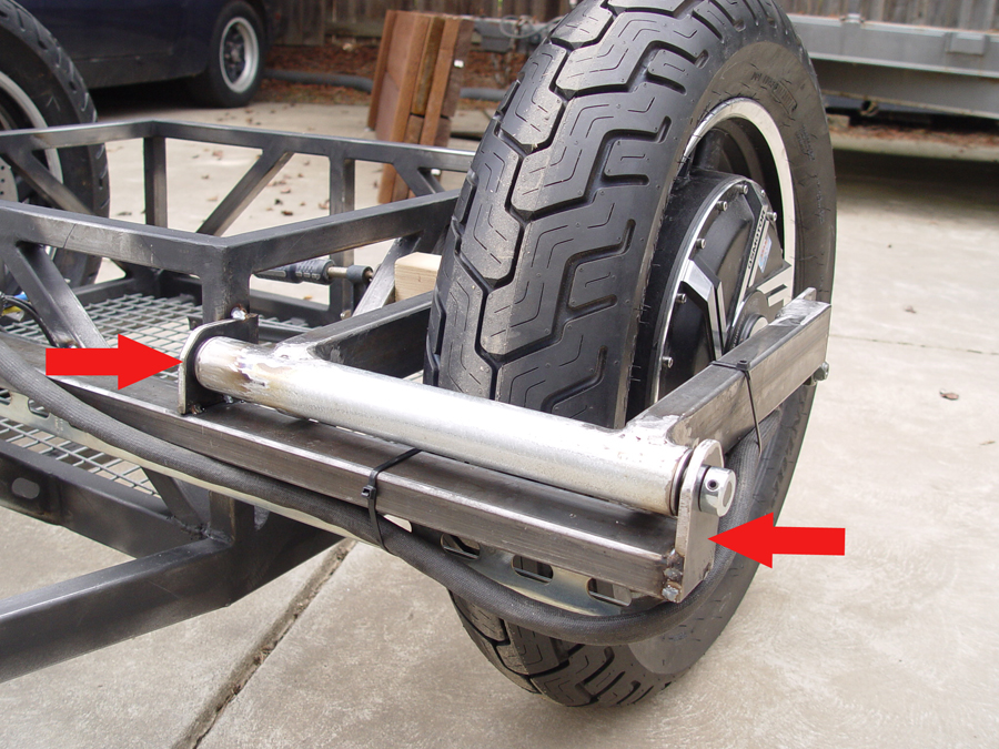
Now for another major head scratching twist in our testing. Based on your assumptions I once again programmed the passenger side controller to limit phase current to 50%. I road tested and now the bike pulls left EVEN WITH 50% CURRENT LIMIT. I'm thinking this means the problem is getting progressively worse. Finding the root cause of the issue is now even more pressing in my estimation.

teklektik said:
Is there any chance your frame is twisting and running the rotor into the caliper under heavy acceleration? Can you pull the pads on that side for a test?

Interesting thought. But because of the way the swing arms are designed I doubt this could happen. To twist the brake caliper would require twisting the swing arm itself, not the trike frame. And I don't think that could happen. Here's a photo of the swing arm and how it is constructed and attached to the frame. You can't see the brake caliper but it is mounted to the swing arm on the inner side of the wheel. As you can see, if the frame twists, the entire swing arm would twist but brake pads would not be twisted into the disk

016a-1.jpg


It isn't a ton of effort to take the caliper off so if I have a chance I might just remove it to satisfy my curiosity.
 
methods said:
I would ride it with the left only...
Then ride it with the right only...

I did this early on primarily to test if the chassis/frame/ or suspension might be at fault...the assumption being if the bike pulled left no matter which motor was connected, then the problem would probably be chassis related. The results were not surprising. With the left motor disconnected the bike pulled left. With the right motor disconnected the bike pulled right. My conclusion was the root cause of the problem was not in the chassis.

This does raise a question I've mulled on a bit, however. I have a 1000W trike I've been riding for about 4 years. It also has dual wheels at the rear. But only one side (the driver side) has a hub motor. The other wheel is just along for the ride. What I find interesting is that I've never experienced the slightest bit "pulling or pushing left" with that trike. In fact, when I was designing this new trike I even toyed with the idea of just putting one 6000W hub motor on the rear rather than going to the trouble of two motors and two controllers and lots of issues to get them to run together. But this new trike, with a motor rated at just three times the size, wants to drive you into the ditch the pulling/pushing effect is so pronounced. I guess I am just surprised at the relative difference between a 1000W motor and a 3000W motor in the torque it can produce and it's inclination to push the front of the bike sideways.


methods said:
Assuming he has a CA for measurements.

Yes, there is a CA on board.
 
cboy said:
Okay. I'll try it.
Please note the CA indicated current draw at WOT for each motor when you do it. This is an indicator of a false positive phase/hall assignment that has been mentioned a few times as a possibility. If one side shows a high current at WOT then the autotune has screwed up. There appears to be one or two adjustments that can be made that affect the autotune, so there may an option or two before going to manual mapping.


cboy said:
Now for another major head scratching twist in our testing. Based on your assumptions I once again programmed the passenger side controller to limit phase current to 50%. I road tested and now the bike pulls left EVEN WITH 50% CURRENT LIMIT. I'm thinking this means the problem is getting progressively worse. Finding the root cause of the issue is now even more pressing in my estimation.
okay - that's not good. The controllers have been switched, the pole count doubled, and now the torque problem is worse than before. This seems to indicate the controller is, in fact, involved somehow. Perhaps one wheel has something odd about the hall placement, etc, that is giving the ID program difficulties with that motor (?). It's too bad the config utility doesn't display the hall map as does the Phaserunner.

I think we're back to not riding it again....
 
I mentioned this in my last response to teklektik but wanted to make note of it to those who might not read through all the posts because I think it might be critical. Early on in my troubleshooting I had programmed the passenger side controller to limit phase current to the passenger side wheel to 50%. This resulted in the bike going straight under moderate to heavy acceleration. But when a number of folks indicated alarm at the need for a 50% current reduction I programmed the controller back to 100% while further testing and troubleshooting could be done. This morning, using teklektik's guidance, I once again programmed the controller to a 50% current reduction. But now the current reduction is having little or no effect. The trike is pulling as hard left with 50% current as it did with 100% current. Head scratching to say the least. And my reading is the problem must be getting progressively worse. So I'm groping for ways to proceed. The factory (QSMotors) has been alerted and they are digesting some of the testing info I've sent them. But if others have suggestions for troubleshooting I'm all ears.
 
Back
Top