2WD trike pulling left when accelerating

teklektik said:
... my knee-jerk reaction is that the best (safest) choice is the pure current mode controller as the one with the simplest torque control and the fewest ancillary behaviors that might conceivably differ in time or magnitude between controllers - which is a prime consideration for the trike. If the mode is as it sounds, it would essentially be a big Phaserunner which is ideal for this application (e.g. see JLE's Solar Trike with dual PRs and Grin motors up front).

The details of the torque mode discussion are a little above my pay grade but bottom line it would seem I ought to be talking with QSMotors about a possible swap of the KlS7230S controllers I have for KLS7230 controllers which Kelly would program at the factory to run in the "pure current" mode. In the best of all worlds it would be great if Kelly and QSMotors conferred on this since QSMotors was the one that put this package together and continues to match the speed control version of the KLS series with the dual wheel options they sell. It would seem to me QSMotors might want to be recommending the "pure current" mode controller when putting together packages for dual motored vehicles.
 
I pinged Fany about the torque mode and she cleared up the mystery. Just to keep the stuff in one place I updated the post on the previous page with the Kelly responses, but here's the summary from the end:

teklektik said:
To summarize - the KLS-S can be ordered with one of three control modes. The Kelly mode names are slightly different than commonly used here on ES:

  1. Torque Mode - this is open loop PWM mode - fast response, no feedback loop, rpm+torque not directly related to throttle setting
  2. Pure Current Mode - closed loop mode where the phase current is dircetly proportional to throttle voltage. This is the same as a Phaserunner and is often referred to as 'Torque' mode because torque is directly proportion to phase current and so the throttle directly controls torque.
  3. Speed Mode - a closed loop mode where rpm is proportional to throttle voltage.

Very interesting.


cboy said:
...but bottom line it would seem I ought to be talking with QSMotors about a possible swap of the KlS7230S controllers I have for KLS7230 controllers which Kelly would program at the factory to run in the "pure current" mode. In the best of all worlds it would be great if Kelly and QSMotors conferred on this since QSMotors was the one that put this package together and continues to match the speed control version of the KLS series with the dual wheel options they sell. It would seem to me QSMotors might want to be recommending the "pure current" mode controller when putting together packages for dual motored vehicles.

To clarify - this factory-programmed mode business is for the KLS-S controllers.

As for the speed vs current modes for two-wheel packages, this choice seems application-dependent. Some considerations:
  • We know that the current PID controllers can correct the current and hence the torque extremely quickly since everything (current sensing, computation, current application) is happening at electrical speed whereas the speed PID controller is burdened with the loop delays of actually accelerating the mass of the vehicle before new meaningful feedback occurs. This gives faster and more precise control for current mode.
  • These controllers are designed for joystick operation which suggests a slow moving vehicle like a wheelchair or tracked vehicle where the user actually controls the two drive motors independently and can automatically correct differences in performance manually as part of the normal driving function. Here there is certainly a lot of gearing so acceleration of the vehicle is not really a consideration making the slower responding speed controller work fine.
  • In the case of a single control like the trike where the controllers receive the same input, turning corners imposes the need for differential-like speed independence of the drive wheels. This is what the pure current mode gives (equal torque but variable speed).

Anyhow - Perhaps QS might like to provide both current and speed options to cover cases of single and dual motor controls.
 
teklektik said:
To clarify - this factory-programmed mode business is for the KLS-S controllers.

Am I correct then that my KLS7230S controllers COULD have been set up at the factory for the "Pure Current Mode" at the time of purchase...had I purchased them directly from Kelly? Or in the alternative, QSMotors could have stocked "pure current mode" KLS-S series controllers for dual wheel applications? Obviously my interest is finding a remedy that will make my trike driveable while not breaking the bank. And from what you have reported, the best remedy appears to be swapping my KLS7230S controllers with the exact same controller BUT with the "pure current mode" option configured at the factory. Or am I missing something in all the details you have provided following your conversations with Fany?
 
cboy said:
Am I correct then that my KLS7230S controllers COULD have been set up at the factory for the "Pure Current Mode" at the time of purchase...had I purchased them directly from Kelly?
Or in the alternative, QSMotors could have stocked "pure current mode" KLS-S series controllers for dual wheel applications?
Yes.

cboy said:
And from what you have reported, the best remedy appears to be swapping my KLS7230S controllers with the exact same controller BUT with the "pure current mode" option configured at the factory.

Yes. These KLS-S controllers appear to do a good job of speed control and I have no reason to believe the current mode versions are lacking in any way. So - yes - that appears to be the best remedy and is what I would do.

  • It would be good if we had some members with experience with dual-drive trikes and this controller who could speak up, but in the absence of that, this is the best I can reason out. Whether there are better Kelly or other controllers for the job is a separate question. And - as I mentioned early on - I have no experience with this particular controller or with trikes at all, so this is not authoritative advice, but the reasoning is out there to be reviewed and challenged.

    I know there is a lot of uncertainty for you in this endeavor, but there have been more than one Phasrunner-based tadpole trike project that were entirely successful. This is not a compelling argument, but from a non-technical view, since the current-mode Kelly behavior appears identical to that of Phaserunners, I think you should feel confident that with this controller change at least you are building in a direction of known design success regardless of the BS I've been posting here... :D

Testing shows differences between these two motors which will be of some concern until testing with the new controllers proves otherwise. I think this can be adjusted away in the current-mode case or at least mitigated to a point where it is not troublesome. That would 100% be so in the case of tandem 2WD, but the need for more accurate balance in the side-by-side trike design leaves some questions. Unless QS has an immediate motor-remedy in mind, I would try to leave the motor-remedy door open with them in case the controller fix strategy is not entirely successful. This should appear to them as an effort on your part to resolve the matter by other means with a need to return to the motor solution only as a last resort. But - your call...

Ideally it would be most expeditious if you could arrange to cross ship the replacements, possibly with a holding charge to be refunded on return of the originals - but those are timing and monetary questions that you need to evaluate.

As a last note - in the event there is reluctance to allow you to return the Kellys, you might ask if they can be reflashed to current-mode at the factory. This would take more time and is a PITA place you don't want to go because of special handling and delays, but if other obstacles develop it might be an option to bring up only as a very last resort...
 
teklektik said:
Yes. These KLS-S controllers appear to do a good job of speed control and I have no reason to believe the current mode versions are lacking in any way. So - yes - that appears to be the best remedy and is what I would do.

After looking at the test results we have generated thus far, QSMotors just emailed saying there appears to be nothing wrong with the motors. And I think, with some minor reservations, that is what you are saying as well. The controllers are doing what they are programmed to do in the "speed mode" and the motors have no obvious operational flaws. So things work, they just don't work together in a dual motor configuration.

QSMotors suggested adjusting down the "Maximum Forward Speed %" on the passenger wheel side to mitigate the pull to the left. In small increments I adjusted all the way down to 50% and there was no noticeable improvement. The trike continued to pull hard left under acceleration at all the settings.

I have now responded to QSMotors with the results of cutting the maximum speed %. I have also suggested the alternative of swapping my existing controllers for identical controllers which would be programmed at the Kelly factory for pure current mode. We will see how they respond.
 
cboy said:
After looking at the test results we have generated thus far, QSMotors just emailed saying there appears to be nothing wrong with the motors. And I think, with some minor reservations, that is what you are saying as well.
Exactly. They do 'work' but clearly do not perform identically. What we hope for is that there is some means for the controllers to be adjusted to compensate for small motor differences and it seems this setup falls short in that regard.

cboy said:
QSMotors suggested adjusting down the "Maximum Forward Speed %" on the passenger wheel side to mitigate the pull to the left. In small increments I adjusted all the way down to 50% and there was no noticeable improvement. The trike continued to pull hard left under acceleration at all the settings.
Strange. I am a little surprised this did not have some effect...

Do you have a wiring diagram (not schematic) of exactly where your power and grounds are connected - including the CA and shunt? Doesn't have to be neat. The exact connection points are important since the voltage isn't the same at one end of a wire compared to the other.
 
teklektik said:
Do you have a wiring diagram (not schematic) of exactly where your power and grounds are connected - including the CA and shunt? Doesn't have to be neat. The exact connection points are important since the voltage isn't the same at one end of a wire compared to the other.

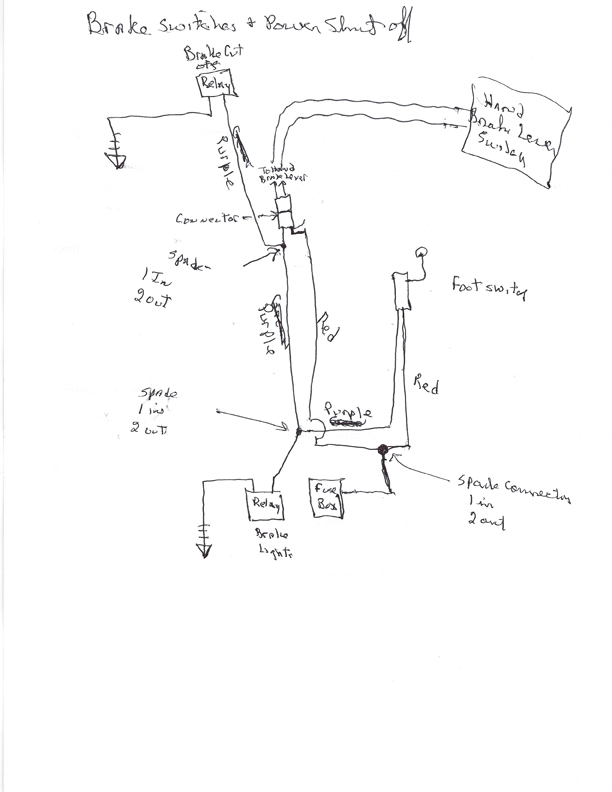
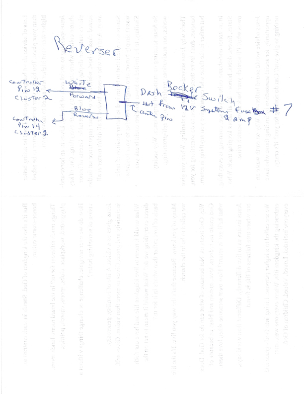
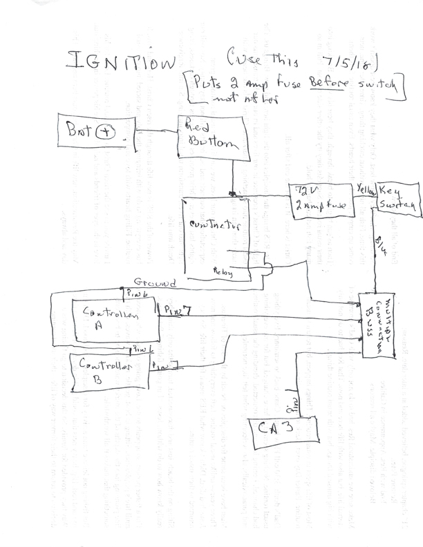
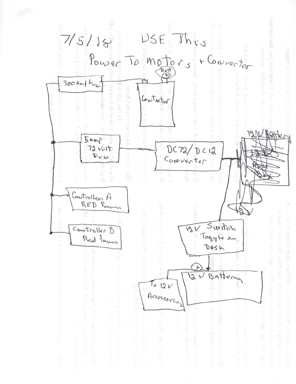
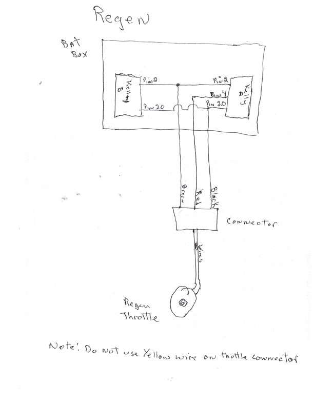
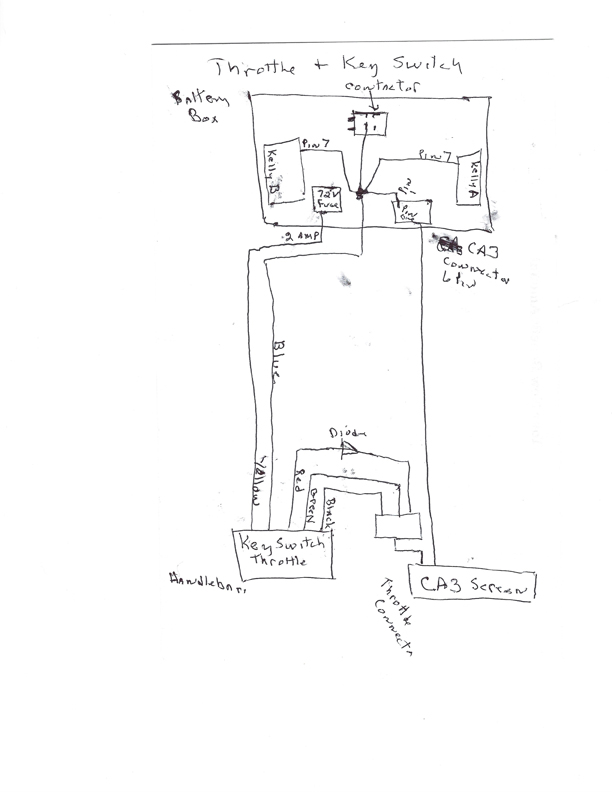
I have some sketches of various circuits, like throttle, regen, ignition etc. but they are very crude. Let me see what I can put together that might be helpful.
 
teklektik said:
Strange. I am a little surprised this did not have some effect...

Your curiosity sets off my curiosity. So I tried the following...these are all passenger side only:

Phase current 100% / Max speed % 20 (this is the lowest possible setting) - no effect pulls left

So then I wanted to see if ANY setting made a difference and tested

Phase current 20% (lowest possible)/ Max speed 20% - Great, now pulls right

Phase current 42/Max speed 42 - Goes straight

Phase current 60/Max speed 60 - Pulls left

Phase current 50/max speed 60 - Slight pull to left

Phase current 50/max speed 50 - very slight pull left

Phase current 46/max speed 50 - Straight

Phase current 46/max speed 80 - Straight

Phase current 46/max speed 100% - Straight

The good news is I finally found a phase current setting low enough to straighten out the bike. The less good news, it doesn't appear from these tests that the max speed % has any effect on the torque issue. Phase current, however, if set low enough, can produce even torque on acceleration. I don't know if these results speak to whether or not the "pure current mode" still looks like the best option but I would think they still support that theory.
 
teklektik said:
Do you have a wiring diagram (not schematic) of exactly where your power and grounds are connected - including the CA and shunt?

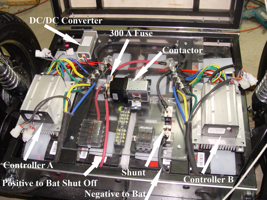
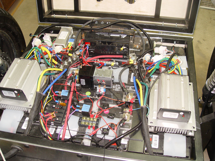
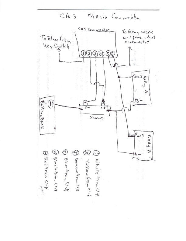
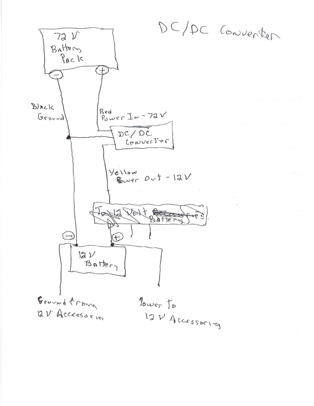
This is what I have at hand. The first two are photos of the electronics box to give you an idea of the layout. The first shot is primarily the high voltage stuff (contactor, controllers etc) and the second shows that same stuff along with the 12 volt system stuff. You can sort of see the shunt and ground wiring points. The other sketches are what I used while I was wiring things up. Maybe just fire off questions about what you can't detect. I don't think this is exactly what you were asking for but I'll try to fill in the blanks as needed.

72 Volt system

036labels-a.jpg


72 Volt system and 12 volt system

030a.jpg


CA3 Main connector

CA3-Main-Connector-6-pin.jpg


DC/DC converter

dc_dc-converter.jpg


Ebrakes

ebrakes-.jpg


Reverse switch

forward_reverse-switch.jpg


Ignition

ignition.jpg


Main controller power

Main-controller-power.jpg


Regen

regen.jpg


Key switch and throttle

throttle-and-key-switch.jpg
 
cboy said:
I don't know if these results speak to whether or not the "pure current mode" still looks like the best option but I would think they still support that theory.
Yes, they do. This strategy just limits the controllers so that they do not interact very much as coupled through the road because the motors are prevented from applying maximum torque. If this reduced power application is okay and the handling is acceptable, then you can stop now. But it's clear that performance is being limited to achieve controller stability. The current-mode approach should not require this compromise so the trike should accelerate harder and get away up hills better, etc.
 
One strategy I use in 2wd systems is to make the grounds of the controllers as precisely equal as possible (other signals as well, but the grounds are the most critical). This means the controllers are bolted together as close as possible to each other, and the grounds joined as close as practical in a single point from which the cables radiate. The large currents flowing in the grounds tend to make differential voltages in the ground which changes each controller's interpretation of what the throttle means by small amounts, which gets magnified by the controller's gain. Each controller, is in some sense an amplifier, taking a small throttle signal and amplifying it into hundreds of amps of current for the motors.
 
Alan B said:
One strategy I use in 2wd systems is to make the grounds of the controllers as precisely equal as possible (other signals as well, but the grounds are the most critical).

Interesting. And it might be applicable to my situation. One controller ground attaches directly to a terminal and then through about 12" of wire to the shunt. The other controller (interestingly the one seeming to produce more torque) attaches to a terminal which then crosses the electronics box with about 20" of wire and attaches to the same terminal as the first controller. Then on to the shunt. So just in terms of total wire to traverse, the second controller has at least 20" more than the first. So I'll put the on my list of potential solutions.
 
Alan B said:
One strategy I use in 2wd systems is to make the grounds of the controllers as precisely equal as possible (other signals as well, but the grounds are the most critical)....

This is certainly helpful in many cases but there are factors that make an unqualified recommendation about grounding invalid - notably for situations with separate throttles that are arranged as dual systems. The unspoken considerations there are that this practice is for single throttle control for the two systems and especially where the throttle is powered from one controller. Although this is a best practice I recommend for those cases, the importance is questionable for modestly powered bikes and situations using a CA3 to supply the throttle. This last point regarding the CA is significant since it can directly eliminate the controller throttle interaction that is the reasoning behind short grounds between controllers.
  • I have a post on my build that also mentions these and other 2WD grounding considerations. There are links to other 2WD builds as well.
  • Teslanv has a really good downloadable 2WD wiring diagram here that embodies all the same considerations I called out but as a nice rolled-up solution. It has cool layer stuff that can be switched on and off that helps understand the different circuits.

Anyhow - this GND issue is where I was going with this line of questions. My initial feeling had been that the strong power bias in one direction we see here could not be explained by the small magnitude voltage reference issues that grounding could introduce. However, that reasoning was based on PWM or current throttle control. At this point I strongly suspect that the veering is the result of a fundamental operating mode causing power divergence when using dual speed-control and a common control voltage. This seemed to make looking for small control imbalances more interesting.

  • A thought experiment: Imagine a bike is rolling downhill with a speed controller - if the actual speed exceeds the setpoint speed of the throttle, the motor power will drop to zero as the controller futilely attempts to 'correct' the speed by ever-reducing the motor power. This behavior is well documented. Now imagine a trike being (largely) propelled by one motor. The ground effectively couples the two motors and so the undriven motor is spinning without applied power. This is the identical situation as the downhill bicycle. The controller on the second side can reasonably regard this as having achieved or exceeded the setpoint speed and remove all power. This appears to be a state where the common throttle setpoint results in one motor carrying the full load, the second motor completely powered down, and both controllers working 100% properly. This state is a result of the interaction of the left and right systems and cannot develop or be explained if they operate independently. This may not be exactly what is happening, but it's interesting because it suggests situations of divergent controller power that could not develop with the more common PWM or current controllers.

    This seems to rely at least in part on a small difference in interpretation of throttle setpoint - which sent me back to the grounding issue...


cboy said:
One controller ground attaches directly to a terminal and then through about 12" of wire to the shunt. The other controller (interestingly the one seeming to produce more torque) attaches to a terminal which then crosses the electronics box with about 20" of wire and attaches to the same terminal as the first controller. Then on to the shunt. So just in terms of total wire to traverse, the second controller has at least 20" more than the first. So I'll put the on my list of potential solutions.
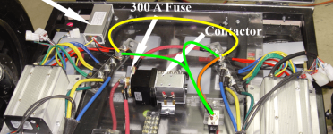
So - this brought me to the request for a wiring diagram showing the actual physical connections - not a schematic showing the logical connections. The first hand drawn illustration looked great and showed what we want, but the photo showed a different story.


trikeGnds.png


Here the problematic wiring is in orange/yellow. I would have preferred to see more or less equal length green connections if I was going to be fussy. That said, you seem to be using huge gauge wire (hard to tell exactly) and the runs are short. This coupled with the independent throttle source and common ground point of the CA3 make me think this is not really a Bad situation. Moreover, the extra wire run to the passenger controller would have the effect of reducing the apparent throttle voltage to that controller, making it run slower - the opposite of the veering we see.

I still do not understand the veering and do not understand how to precipitate the wacky state I described above, and so can't discount this very small effect (probably only 1%-2% of throttle) from the yellow/orange wiring choice. That said, it's not high on my 'suspect list'. So, perhaps not a best practice, but I think not a likely cause.
 
teklektik said:
That said, you seem to be using huge gauge wire (hard to tell exactly) and the runs are short.

4 awg to be exact, for the battery pack, contactor and main controller wiring, both positive and negative. This was a recommendation from Kelly.

Hopefully we will have some additional data to mull over in a couple hours. Kelly has sent me firmware which will allow me to re-flash the controllers so that they operate in pure current mode. I'm on my way out to the shop to do that now and then make some test runs and tinker with fine tuning, if necessary. That should tell us a good deal.
 
Short, low impedance grounds and single point grounding won't hurt and it can solve problems that are not easy to understand or analyze, and can be difficult to band-aid in other ways.

The fact that this system has even torque when accelerating slowly, and strongly differential torque when accelerating hard points to something exactly like grounding to be a core issue. The primary difference between the two experiments is magnitude of current flowing through the system. The effects of large currents on the system controls is primarily on the ground side. While we have not identified a simple theory that explains the effect, it is very likely grounding related. Improving the grounding system will not hurt, and it may reduce or solve this or other problems which have yet to be observed.

Enough about grounding, let's move on to something else. In this particular case reducing the gain of the speed loop may also provide improvements. PWM throttle systems generally exhibit about six times the gain of a current loop system (even more with high power motors and controllers), and this is part of the problem - too much system gain. Speed throttle systems have adjustable gain, and likely have higher overall gain than the PWM throttle. Reducing the gain will tend to reduce the difference between the wheel torques. Reducing it too much may cause other issues like throttle delay, so it is a trade-off.

Good news on the re-flashing appeared while I was writing this post. This should greatly lower the system sensitivity to these issues. Good luck with the re-flashing.
 
Delay in re-flashing the controllers. The install program has a slight glitch and I can't get the full bootloader screen to show up on my display...it's missing two essential buttons. So it may take a bit of time to work this through with Kelly.
 
Keeping away so as to bring the different perspective:

Started reading a few pages back
Skimmed the last page or two

... I saw a side by side freewheel test...
I would expect those to come in line on line. 10% is a major difference in two motors that are supposed to be "the same". When I was importing motors and freeWheeling them - after hundreds and hundreds - they all came in "the same" (as measured to CA resolution). The only motors that ran different had bad halls, rubbing dust washers, or tires (Tires greatly affect freewheel speed and therefore current).


Yea - By Chinese QC Standards (that we negotiate... so not their fault) motors could be 10% off... because few buy them in pairs.

...

Sticking with the theme of "What is so different about this guy" -
Well... you may notice that running 2 controllers is highly uncommon.
Yes - on paper - it all sounds DC Great
In reality, on the scope, you will see "great fighting" going on between those controllers.

To the degree that - with many controllers - trying to run two from a single throttle simply wont even work!

Order of Operations: (If not done already)

1) Confirm the freewheel tests are off by that much by using 1 controller to operate two motors, one at a time.
IF - You find this to be true - there is not much more to explore. The motors are different and therefore should either be paired, or ... operated differently. Trouble is... In Speed Mode the phase current limits (unless you are on them) wont help... so when you command the controller to go from Current SPeed to New SPeed, if they are not at Full Load, then each will apply torque but 10% different.

10% is a big difference in a balanced system. In a balanced system we are looking at maybe... 1/10th% error for them not to fight.

2) If that test gets delayed (or you order a new pair of motors, or one more motor) you may want to work on decoupling. You have one battery but two controllers. The battery can provide a steady DC but the controllers want this horrible choppy bursty power. Most of their strange needs are covered by the caps internal... but not all... and this is an unregulated industry.

You may consider running some large caps at the controller inputs. This will help to keep their noise local, help stop currents from flowing back and forth between their grounds...

Ya see...

If you are running a common ground throttle
And currents are flowing thru ground
That gets real confusing for a system which is looking to make decisions around 10's of mV

So
Cleaning that up to the degree possible.

IN THE PAST
I have build dual-throttles in the following way:

1) Disassemble the throttle and confirm it is a hall throttle.
2) Disassemble a second throttle and hack away from it the linear hall sensor
3) In my case, glue the sensors one atop each-other so that one is slightly closer to magnet (front wheel)
4) In your case... pull both hall sensors... then put them back in side by side or in some way that they see equal magnetics as measured by your Fluke DMM

...

In doing this you are true-Isolating (AC and DC) the throttle controls so any noise in the system is eliminated as a factor

Finally.....

Have you considered what would happen if you wired both motors to a single controller?
Pure disaster experiment... but interesting.
No doubt that as soon as you had to turn the motors would fight eachother and great sadness would ensue...

But
I like to keep an open mind as things like this work sometimes (like two motors mechanically bound by a shaft)

Good luck
and.... remember to buy tools thru this...
As it is simply training camp. Your bike will work again soon - we just have to send out the OTA clearance.

thanks,
-methods
 
P.S.

Most people running dual controllers are doing so in a tandem configuration.

Speed mode is a confusing mode for many people.
It can be visualized in 2 ways

1) Big difference in current speed vs demanded speed
This is like flipping an OpAmp into saturation - the current limit dominates

2) Tiny difference in current speed vs demanded speed
In order to provide a smooth ride some hysterysis and ... calm... around convergence is required. IF the controller were to try and apply full current right to the point of unity (target speed) it would overshoot, oscillate, and would suck. Therefore, we know, that as a controller converges on its target the amount of feedback is reduced.

3) Visualizing this as two windows (or a linear progression) it becomes clear why a little noise on the throttle wires can make a big difference in side by side performance... Especially if one throttle is wired differently than another. These are extremely noisy systems.

Have you by chance...
Wired up 2 separate throttles... (one on each side)
And gone at it like that?

...
I mean... We already found the 10% difference in your motors... which I am sure is the cause of your sorrow... but running dual throttle may help you refine some of the 2nd order behavior you may find once you get it running straight.

In Tandem... the motors "shift responsibility" forwards and backwards... This may appear as an equal sharing... but on a scope it is a system in oscillation, converging on balance. They try to do this same thing on your bike... but its a run-away situation... any imbalance is magnified (instead of compensated for)

So

My suggestion is to chum up to the supplier
Let them know that they need to send ONE replacement motor
Test it against the other two, find its best match
Return the other motor

MAKE SURE

You are running the exact same rubber
To same inflation
Etc... better yet... do the tests with no tire on

The two motors need to test out identically on the same controller
(Case closed on that)

-Schindler
 
methods said:
... I saw a side by side freewheel test...
I would expect those to come in line on line.

Just a note on this. I don't know that I would label my testing "side by side". And I think my methods are a bit too crude to get overly precise with the results. The testing was done on one side at a time with the other controller/motor disconnected. A more perfect test would be to have separate monitors, one on each controller, with a single throttle input, spitting out data to a log which could be captured and reviewed in great detail later. Plus each of my tests was done "by hand"...with human control of the throttle which could be less than identical during each tests. This is born out over multiple testing I've done where the results vary by small amounts from test to test. The tests have always skewed in the same direction in terms of left side vs right side...but by different amounts. Using my test methods I can't image the results coming in line on line. I'm guessing that can only happen with much better equipment and techniques than I have available.

BTW, just noticed you are in Santa Cruz, so not too awfully far away. We are in the Merced/Atwater area and, ironically, our family has just made an offer on some property about 15 minutes out of Santa Cruz.
 
Alan B said:
Short, low impedance grounds and single point grounding won't hurt and it can solve problems that are not easy to understand or analyze, and can be difficult to band-aid in other ways.
My point is entirely that GNDs should nominally be applied for a reason and in this case the common Ground point/equal length GND wire scheme is designed to mitigate effects of a very specific situation of controller interaction with a common throttle.

There is more than one 2WD approach and I believe it is misleading to not qualify a recommendation for this strategy so that those who are building 2WD for which it does not apply are not misled into believing it is of benefit. For instance - suppose someone wants to build a straight-up motomech-style independent 2WD system with two throttles, with or without a common battery. There is no possibility of throttle interaction and no benefit from the perspective of control interaction in tying the GNDs to a common point, using equal length wires, or co-locating the controllers so these ground runs are short. In point of fact, it would be better to position the controllers close to the motors with short phase wires - exactly the opposite. So - I think a few words to clarify or qualify the situational relevance are valuable and can arguably prevent misunderstanding leaving the issue of "won't hurt" for the listener to evaluate.


Alan B said:
The fact that this system has even torque when accelerating slowly, and strongly differential torque when accelerating hard points to something exactly like grounding to be a core issue. The primary difference between the two experiments is magnitude of current flowing through the system.
You are conflating common R/L speed with 'even torque' (even phase current) at low speed. While this may be true regarding the average torque, the collected/plotted data shows wide phase current excursions as the controller tries to accelerate the huge trike loaded with lead acid batteries. These excursions are the result of controller gain, not setpoint offset (grounding). In the case of going WOT off the line, the small throttle offset (about 0.016V at 80A) is the smallest possible percentage of the overall setpoint error (about 4.25 volts or 0.3%). This high current, high setpoint error case is the situation that shows the least effect of offset. The maximum effect should be at high current and low setpoint error. This is opposite of what we are seeing. Furthermore the offset is the opposite direction of the observed veering. On the face of it grounding does not appear to be a direct cause of the veering which appears large, stateful, has quick onset, and is different than the interaction jitter or oscillation we might expect with setpoint interacton.


Alan B said:
In this particular case reducing the gain of the speed loop may also provide improvements. PWM throttle systems generally exhibit about six times the gain of a current loop system (even more with high power motors and controllers), and this is part of the problem - too much system gain. Speed throttle systems have adjustable gain, and likely have higher overall gain than the PWM throttle. Reducing the gain will tend to reduce the difference between the wheel torques. Reducing it too much may cause other issues like throttle delay, so it is a trade-off.

Yes, this is certainly a valid approach and I think goes much more directly to the cause of the veering than ground issues.

Is some respect this has a similar effect as reducing the maximum phase current (demonstrated to work) where the gain multiplier products are scaled down. The plotted data clearly shows excessive gain. Speed controller tuning can be quite frustrating (FWIW I wrote the speed tuning guide and devised the speed tuning algorithm in the CA Guide). With a heavy vehicle, gains must be very modest because overshoot of the vehicle is reversed only by allowing the vehicle to naturally decelerate. This is unlike phase control where overshoot is quickly and actively addressed by reducing current. An intrinsic problem with speed control is that the although the controller remedies overshoot the same way by reducing current, the effect of actually reducing vehicle speed happens very much later making the system response much slower.

I originally discarded the idea of trying to re-tune the PI controller as a perhaps challenging task with no PI tuning expertise in hand, two controllers, and poor to no instrumentation. The potential difficulties did not seem worth effort to get a vehicle with restrained performance that still was saddled with the enforced equal-wheel-speed issue for turning (it fights to go straight no matter what).

However, when looking at the plotted data while musing about the thought experiment above, the effects of the extreme phase current excursion around the 3.5 second mark lead me to the same conclusion about the causative effect of gain and overshoot. This data was taken at different times but presents a reasonable hypothetical. There we see a situation where one controller is producing all of the instantaneous torque and the other essentially none. If the setpoints are misaligned properly, it seems this might reasonably gravitate to the stable all on/all off state described above (veering) with the integral error term tending to prevent the OFF controller from resuming operation in spite of small setpoint error changes. I could be very wrong here, but I think this may be what is happening.

So - to be clear, gain may be involved, but the core problem is the speed controller. Reducing the gain and slowing system operation looks to be means to make the best of a problematic controller choice.

Anyhow - I am frankly delighted to see the Kelly field programmability since the OP now has the option to restore speed controller operation in case this armchair reasoning has gone astray.... :)


WOOOHOOO

Finally got the controllers re-flashed for pure current mode. Long hard battle getting the install program to work. Totally a problem with my old XP laptop that doesn't go beyond 1024 x768 screen resolution. And the install program was written with wider screen resolution. So of the most important "buttons" to do the install were not visible on my screen. So it took me almost a day to figure out how to get a big screen monitor hooked up and working to get wide screen resolution. But finally got it going this morning and did the re-flash.

And the best news of all, the bike runs straight and true with full, 100% phase and 100% speed in both controllers. What a difference. It is like a totally different vehicle now. Have to do some much longer road test runs but I can't imagine needing anything more than a few tiny tweaks. One side note to anyone doing this in the future. When you reflash the controllers it resets everything you previously programmed into the controllers, like reversing the wheel direction (don't ask how I discovered that). And you have to rerun the angle identification program. So basically you are starting over in terms of any programming...but that part is fairly easy.

Wow...I'm just elated. And a huge huge shoutout to Fany and Kelly Controllers. They really came through even though I had not purchased the controllers directly from them (but rather through QSMotors) they really went the extra mile to see if this change would work for my setup. Also a huge shoutout to Teklektik and everyone else who contributed to this rather long and difficult thrashing of the problem. I learned a ton along the way. And hopefully this thread will help others who might use a dual hub motor configuration with the kelly KLS controllers. NOW I'm going for a nice lone ride...to enjoy the breeze...and not pull to the left!
 
cboy said:
The testing was done on one side at a time with the other controller/motor disconnected. A more perfect test would be to have separate monitors, one on each controller, with a single throttle input, spitting out data to a log which could be captured and reviewed in great detail later.
Frankly, I was impressed with the ingenuity to get the data.

Even though it is not side-by-side and illustrating interaction which would be very revealing, it does show quite a bit about how the autotune has worked and what the controllers are really doing. It also shows the controllers working similarly and pretty well at maintaining the setpoint throttle speed. This is important since it pretty much takes controller problems off the table - whatever is happening seems to be a result of the controllers working together that makes the autotune inappropriate or is aggravated by some nuance of wiring - lends focus to the problem...

The problem with not having dual instrumentation is an obstacle and one of the reasons I was originally unenthusiastic about trying to re-tune the PI controllers. I have spent countless hours tuning a speed controller for a heavy cargo bike and I had instrumentation and only a single drive wheel. It's not too hard to get something to sort of work, but throw in some inclines and different speeds of operation and it can make you want to take up hard drinking....

EDIT - Whoops - cross-post - great news above!!!
 
I have followed your build thread with great interest and admire the work you're doing for disabled riders.
I have also been following this "trouble shooting" thread and must make a deep bow for your perseverance and the help others have offered to get this all solved. Great to read that it seems to work now how you've intended it to. I hope you'll update your build thread with the rest of the build and give a ride review once you have more miles to report about.
Good luck and enjoy!
 
Back
Top