3-192S Arduino BMS (using BQ76PL536A)

dmwahl said:
Very interesting link I just ran across on Tesla's battery packs: http://www.teslamotorsclub.com/showthread.php/34934-Pics-Info-Inside-the-battery-pack
Also interesting that they're using the same battery management chip as my project, very cool 8)

Great find! Note BQ76PL536 is fine for Tesla as they have only 6 groups of cells per module. I would prefer LTC6804 for ebike because one chip can support more cells in series.
Anyway interesting that cell balancing in Tesla modules is such a low power!
 
jayx said:
dmwahl said:
Very interesting link I just ran across on Tesla's battery packs: http://www.teslamotorsclub.com/showthread.php/34934-Pics-Info-Inside-the-battery-pack
Also interesting that they're using the same battery management chip as my project, very cool 8)

Great find! Note BQ76PL536 is fine for Tesla as they have only 6 groups of cells per module. I would prefer LTC6804 for ebike because one chip can support more cells in series.
Anyway interesting that cell balancing in Tesla modules is such a low power!

I've heard rumors that the LTC6802/3/4 are more difficult to get working and buggy, but I haven't tried them myself so I don't know if it's true or not. The BQ76PL536A has been rock solid in the applications I've used it in. Regardless, the overall board size, cost, and function of a single LTC680x vs 2x BQ76PL536A is basically the same.
 
dmwahl said:
I've heard rumors that the LTC6802/3/4 are more difficult to get working and buggy, but I haven't tried them myself so I don't know if it's true or not. The BQ76PL536A has been rock solid in the applications I've used it in. Regardless, the overall board size, cost, and function of a single LTC680x vs 2x BQ76PL536A is basically the same.

Cost probably yes, but overall board size - LTC680x package is smaller than BQ76PL536A and support 2 times more cells (although looks like it require another chip to handle Isolated SPI communication). Also BQ76PL536A has power pad so impossible to solder without special equipment. Have seen that comment LTC680x is buggy, but no details what's the problem exactly. Not sure about difficulties to get it working, looks like there are Arduino libraries ready to use.
 
jayx said:
Cost probably yes, but overall board size - LTC680x package is smaller than BQ76PL536A and support 2 times more cells (although looks like it require another chip to handle Isolated SPI communication). Also BQ76PL536A has power pad so impossible to solder without special equipment. Have seen that comment LTC680x is buggy, but no details what's the problem exactly. Not sure about difficulties to get it working, looks like there are Arduino libraries ready to use.

My point was more that board size is not really determined by the LTC or TI chips themselves, but by the other required components. Isolation is only required for either chip if the attached microcontroller is powered by a separate power supply. That would be helpful for systems where the master control board is powered by a separate power supply (ie a 12V accessory battery) and the cell monitor sections are powered directly from the high voltage pack.

Special soldering equipment is kind of assumed for both parts, sure you can solder them by hand but neither is intended to be used this way. Soldering the power pad with a normal iron is actually relatively easy, you just need to include a few open vias or through holes large enough to wick the solder through and ensure they're not coated with solder mask. You can also put a little solder paste on the pad before placing the part and heat from the other side. Once you see the solder paste has melted and wicked through the vias then remove the heat. Personally I have my own reflow oven, but it can be done by hand.
 
dmwahl said:
My point was more that board size is not really determined by the LTC or TI chips themselves, but by the other required components. Isolation is only required for either chip if the attached microcontroller is powered by a separate power supply. That would be helpful for systems where the master control board is powered by a separate power supply (ie a 12V accessory battery) and the cell monitor sections are powered directly from the high voltage pack.

Special soldering equipment is kind of assumed for both parts, sure you can solder them by hand but neither is intended to be used this way. Soldering the power pad with a normal iron is actually relatively easy, you just need to include a few open vias or through holes large enough to wick the solder through and ensure they're not coated with solder mask. You can also put a little solder paste on the pad before placing the part and heat from the other side. Once you see the solder paste has melted and wicked through the vias then remove the heat. Personally I have my own reflow oven, but it can be done by hand.

I’m still not convinced PCB size will be the same, but not going to argue as the difference would be rather small.
Didn't think about the method you've described for powerpad soldering, certainly it can be done this way. Just removing the chip (in case it was blown, etc.) will still require more advanced equipment.

Anyway, I was going to build something with LTC chip, but your project is so advanced I’ll better spend my time helping you. Do you have PCB you’ve mentioned a month ago ready yet?
 
I have a few bare 6S PCBs, and was just about to order more single IC boards with a few extra features (temp sensor, GPIO, GPAI, and PTC fuses to protect against short circuits). The new boards will be daisy chainable using standard 10 pin (2x5) cables. The 4 chip PCB is basically done, I'm cleaning up the routing but I've waited on ordering any since they're larger and take longer to build. Once I have the firmware mostly worked out with the 6S boards I'll make some of the full size boards. Send me a PM if you're interested in either some bare PCBs or built up boards. At the moment what I'm mostly looking for help with it the software, I have the basic code working for error correction, cell voltage reading, turning balance resistors on/off, and temperature sensor reading.

The BQ76 ICs themselves are pretty durable, I've shorted cell wires together accidentally and burned up traces, exceeded voltage ratings on pins, and have had no failures. Probably helps that all of the pins are relatively high impedance, so the damage from faults tends to be external.The center pad is not required for operation, so for development you could always leave it disconnected.
 
dmwahl said:
The main thing I'll need help with is firmware, there was someone helping me with that a while ago and he had a good start, but I haven't been able to get in touch with him so it's back to the start. I have all the basics worked out, but need someone with the ability to create a complete firmware. I plan on offering the board to anyone who can help with software at cost.


Um... sorry Dave, that would likely be me. Tried to call ya just now, what can I say things have been F*C&ED up here for me for a while but I'm happy to rewrite the firmware for 12-24S stackable using the BQ76PL536A and Arduino. I did finish mucking about with the developer board (3 in stack config) and a bit more playing about but for the "paying" project I had been working on (before falling into the abyss) I actually worked it out in a similar fashion to Fetcher/Gary Goodrum TL431 chip style with a single ATTiny marshalling every 2 cells and feeding a master BMS Arduino1280 as the "MCU Brain". This was not so much a better design electronically but conformed to the clients specifications and even supported HOT SWAP of their 2S{X}P blocks which they chose to go with (each 2S had its own slaver unit).

To be perfectly honest I had quoted them a great price for the R&D, PCB Design and Firmware which was around 3500 USD (I know cheap labor but we had common goals I thought). Worst part is, when I completed the job and produced 12 working prototypes (24S 80AH 30/40C Lipo worth) the customer had me assemble the first test pack and then never bothered to even pay the balance of 3K (I only charged 500 upfront for cost of materials). Adding insult to injury, I found out about 4 months ago, they knocked my design and my firmware off (I set the lock bits but it's a damn close knock off) and are now mass producing (or having them produced in mass) in fricking China. Since they are not a 100% copy and they are actually not a US company but rather a Chinese company who fronted via a Delaware USA corporation... I really have no recourse.

Before you ask (any of you, not just dave)... The design while function is far from efficient as it's design intent was modular and hot swappable, something we don't care for... not to mention the parts cost, BOM, surface mount (except the bleeders) assembly difficulty (me and average joe) and finally... while it would serve the client right if I dumped all publically, I won't stoop to their level nor drop IMHO total crap on the market or even the ES DIY crowd.

That said... I am available to write up the firmware / adapt the old firmware (nah I'll start from scratch, I've come along way) but I would like to discuss some hardware stuffs with you - if not included in the basic Arduino BMS offering then at least plug and play via headers to enhance functionality.

Give me a call when you have time, you have the number :)

Regards,
Mike aka mwkeefer
 
mwkeefer said:
dmwahl said:
The main thing I'll need help with is firmware, there was someone helping me with that a while ago and he had a good start, but I haven't been able to get in touch with him so it's back to the start. I have all the basics worked out, but need someone with the ability to create a complete firmware. I plan on offering the board to anyone who can help with software at cost.


Um... sorry Dave, that would likely be me. Tried to call ya just now, what can I say things have been F*C&ED up here for me for a while but I'm happy to rewrite the firmware for 12-24S stackable using the BQ76PL536A and Arduino.
...
Give me a call when you have time, you have the number :)
No worries, life happens. I've been pretty busy with a 10 month old too as you can imagine. On the plus side he seems to have an interest in battery systems, hopefully it will turn into an interest in more than just putting them in his mouth... (fortunately he hasn't been successful).
 
Now was time to me to see your project, very nice ;)
It seems like we share the same vision, so I think we should collaborate. If you want to go to LTC640x in some moment, you can use the files we are going to upload, or any other help you can count on us too.
 
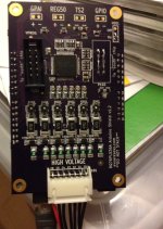
It took a few revisions, but I finally am happy with the schematic and layout of my BMS boards. I ended up going the modular route for now, each board handles 3-6 cells, and can be expanded up to 192 cells via a standard 10-pin (2x5) cable. The stack of BMS boards fits onto an Arduino Uno.
1.2 photo.JPG
The only missing part before it could go on a bike (or elsewhere) is a power supply. I'm currently powering the Arduino board through my computer's USB port, but am working on a design to step down the full pack voltage to 5V to power the Arduino. It will bypass the inefficient 5V regulator on the Arduino, thereby substantially lowering the power draw. I'm estimating around 50-100uA of average draw from the battery pack when using the ATmega's sleep modes. (Using one of those portable cell phone battery chargers with a USB port to power the Arduino instead, main pack draw can theoretically be as low as 12uA due to the BQ76PL536A chips). It will be limited to 140V main pack voltage, which is enough to get up to ~32S lipo. And because I know someone will ask... Yes, the current draw is even across all the cells, so it will not cause imbalance of the pack.

Sample of the board readings below. The two numbers after cell readings are temperature, the first is an on-board thermistor to monitor BMS temp and the second is off-board for monitoring cell temps (not connected at the moment). When I took the readings below the board was cooling down after a test of the balance resistors, hence the decreasing temperature readings. A reading of 4500 corresponds to about 25C, or 76F:
Code:
Cell 1: 3284.00mV
Cell 2: 3290.38mV
Cell 3: 3279.31mV
Cell 4: 3280.84mV
4508.00
30.00
---
Cell 1: 3285.00mV
Cell 2: 3290.38mV
Cell 3: 3279.31mV
Cell 4: 3280.84mV
4506.00
29.00
---
Cell 1: 3285.00mV
Cell 2: 3290.38mV
Cell 3: 3279.31mV
Cell 4: 3280.84mV
4504.00
28.00
---
Cell 1: 3285.00mV
Cell 2: 3290.38mV
Cell 3: 3279.31mV
Cell 4: 3280.84mV
4502.00
30.00
---
Cell 1: 3284.00mV
Cell 2: 3290.38mV
Cell 3: 3279.31mV
Cell 4: 3280.84mV
4500.00
29.00
 
Sorry if this is a dumb question but do I understand correctly that this board checks each cell voltage separately, not only groups?
 
k2nguru said:
Sorry if this is a dumb question but do I understand correctly that this board checks each cell voltage separately, not only groups?
I'm not sure what you meant by groups, but yes it checks each cell voltage.
 
I am more than interested in helping you code. Are you talking about coding the arduino module? I have plenty of experience in that. I also have lots of free time till school starts up for me again for the spring semester.
 
Ragonamuffin said:
I am more than interested in helping you code. Are you talking about coding the arduino module? I have plenty of experience in that. I also have lots of free time till school starts up for me again for the spring semester.
Thanks, I'll PM you.
 
I've actually been working on a project similar to this using the bq76pl536 and an NXP microcontroller for use as a 12V replacement for a car for a school project. I don't know if you remember me, Mike, but you actually helped me build my first ebike! (a 2Kw gng)

I can't believe I never checked ES to see if somebody would be working on something similar, but I would love to help with firmware development, as well as maybe get some tips from you more experienced guys on the hardware interfacing.

-Karfax
 
mwkeefer said:
dmwahl said:
The main thing I'll need help with is firmware, there was someone helping me with that a while ago and he had a good start, but I haven't been able to get in touch with him so it's back to the start. I have all the basics worked out, but need someone with the ability to create a complete firmware. I plan on offering the board to anyone who can help with software at cost.


Um... sorry Dave, that would likely be me. Tried to call ya just now, what can I say things have been F*C&ED up here for me for a while but I'm happy to rewrite the firmware for 12-24S stackable using the BQ76PL536A and Arduino. I did finish mucking about with the developer board (3 in stack config) and a bit more playing about but for the "paying" project I had been working on (before falling into the abyss) I actually worked it out in a similar fashion to Fetcher/Gary Goodrum TL431 chip style with a single ATTiny marshalling every 2 cells and feeding a master BMS Arduino1280 as the "MCU Brain". This was not so much a better design electronically but conformed to the clients specifications and even supported HOT SWAP of their 2S{X}P blocks which they chose to go with (each 2S had its own slaver unit).

To be perfectly honest I had quoted them a great price for the R&D, PCB Design and Firmware which was around 3500 USD (I know cheap labor but we had common goals I thought). Worst part is, when I completed the job and produced 12 working prototypes (24S 80AH 30/40C Lipo worth) the customer had me assemble the first test pack and then never bothered to even pay the balance of 3K (I only charged 500 upfront for cost of materials). Adding insult to injury, I found out about 4 months ago, they knocked my design and my firmware off (I set the lock bits but it's a damn close knock off) and are now mass producing (or having them produced in mass) in fricking China. Since they are not a 100% copy and they are actually not a US company but rather a Chinese company who fronted via a Delaware USA corporation... I really have no recourse.

Before you ask (any of you, not just dave)... The design while function is far from efficient as it's design intent was modular and hot swappable, something we don't care for... not to mention the parts cost, BOM, surface mount (except the bleeders) assembly difficulty (me and average joe) and finally... while it would serve the client right if I dumped all publically, I won't stoop to their level nor drop IMHO total crap on the market or even the ES DIY crowd.

That said... I am available to write up the firmware / adapt the old firmware (nah I'll start from scratch, I've come along way) but I would like to discuss some hardware stuffs with you - if not included in the basic Arduino BMS offering then at least plug and play via headers to enhance functionality.

Give me a call when you have time, you have the number :)

Regards,
Mike aka mwkeefer

sheesh ... what are the names of these blokes that ripped you off?
 
I have a fully functioning board as of a few weeks ago. For a variety of reasons, I haven't decided yet if it's worth my time to sell them on here. They're relatively expensive, and programming, as mentioned before, is a major task. I'll try to get a photo up shortly, sorry for the silence lately.
 
Quick video of it in action, balancing my 10Ah 16S pack. Balance current is about 500mA, and it gets HOT. My IR gun reads about 125C on the big resistors, board is around 60-70C while the room is about 20C. The 4 wires running off the Arduino board are serial for monitoring on my computer.

[youtube]ubcytw4zfh8[/youtube]

At the moment it's not for sale, so while I appreciate the interest I will not be selling individual boards right now.
 
Hi.
Iam very intrested in this board, and to hear more about the funktunality. I know it is not for sale atm. Please contact me private. Danjensen89 Elephant-nose-a g m a i l dot c o m
 
Hey, Ive been working on a BMS with a partner as a School research project we built our own arduino on the same circuit board with the BQ76xxx! We finished our hardware a few months ago and are transitioning into writing code.

We have the intentions of modifying the SPI library by adding more functions so that the Main.h code file on the arduino is very clean. The goal is to have an arduino library that someone with very little arduino or coding experience can modify the main code to achieve what they desire for a variety of purposes from E-bikes and e-boards to large size portable boom boxes using lipo and pumping out hundreds of watts.

Seeing that you're more than 2 years into this project, do you have any suggestions or warnings to look out for as we try to accomplish this?

Thanks Guys
 
dashimsta said:
Hey, Ive been working on a BMS with a partner as a School research project we built our own arduino on the same circuit board with the BQ76xxx! We finished our hardware a few months ago and are transitioning into writing code.

We have the intentions of modifying the SPI library by adding more functions so that the Main.h code file on the arduino is very clean. The goal is to have an arduino library that someone with very little arduino or coding experience can modify the main code to achieve what they desire for a variety of purposes from E-bikes and e-boards to large size portable boom boxes using lipo and pumping out hundreds of watts.

Seeing that you're more than 2 years into this project, do you have any suggestions or warnings to look out for as we try to accomplish this?

Thanks Guys
Having a library is a very good idea, it's exactly what I did and it's indispensable. The communication isn't terribly complicated, but getting the sequence of commands just right takes a bit of trial and error. A scope or logic analyzer will be very helpful, especially at first. I wouldn't modify the spi library though, if you look at the existing code it's fairly simple. I don't recall if it uses that stupid "digitalWrite" command or not, but for the most part it was relatively optimized last I looked at it. (I dislike digitalWrite because it uses about 10x the cpu cycles necessary and only writes a single bit at a time. Fine for hobby and prototyping, but too slow if you want a fast product.) Start by getting the BQ chip itself communicating, then worry about optimizing SPI or other libraries.

That said, the problem you may run into is not so much making a user friendly library (which would be awesome), but that the hardware itself is relatively expensive. The BQ76PL536A itself is ~$5-10 depending on quantity, and when you add in the rest of the required hardware it's easily a $30 bill of materials, plus PCB and assembly. Large quantities will of course lower the cost, but it's just not a hobby oriented product.

All in all the BQ76PL536A (and it's auto rated counterpart BQ76PL536A-Q1) are fantastic parts for BMS design, but they are quite complicated and labor intense to get going. It took me several iterations to get the hardware just how I wanted it, and many more hours of time getting the library and firmware fine tuned. The nice part is it's very scalable, so you can start with a 3-6S design and later on add more with minimal code changes.
 
Back
Top