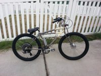
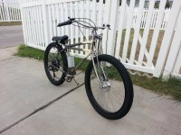
35 MPH cruise, 10 mile range, looking for tips

wesnewell said:
You can run it continuous at 35mph, assuming there's not a lot of drag. At takes a lot more voltage and power to get to 40mph. I wouldn't run it at 40mph more than 5 minutes in 100F heat we have here in TX. Bare in mind I've never tried to push it like this so couldn't say for sure when you'd reach the point where damage would occur. With stock voltages there should never be a problem since you will likely never hit anything above 35mph on level ground. This would be the same for common Clyte and 9C motors from what I can tell.If you want to cruise over 35mph, be practical and get a bigger motor.

Excellent, thanks Wes! I wanted to build this bike with the idea that should I want to go to a bigger motor in the future that it would just be a matter of swapping out the rear wheel, hence the 24s. For my current needs 35 MPH cruising speed should be perfect, but who knows where the bug will take me in the near future.
 
So the day after I laced my wheel I took it over to my LBS to true it up. Their wheel builder was there and had never done an electric hub motor and was very interested in the build. He asked what kind of spoke prep did I use... my response was "Hope?". LOL. So just for the experience he rebuilt the wheel using their spoke prep and just charged the regular $15 truing fee :D

He said that I did a pretty good lacing job for my first time, though. Thanks to everyone here, especially Wes, Blackssr, and Dogman (I checked out your lacing page).

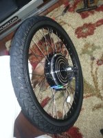
I picked up some 22mm Velox rim tape and mounted the rear tube and tire to the rim. One issue I ran into was the valve stem hole was a little small for my tube, so only the metal part of the valve stem would fit. I am not sure if it was because of the rim or because I was using thick Kenda downhill tubes? A couple quick swipes with a round file and it fit nicely. I will be sure to check my front rim as well.

The digital bathroom scale said 20.5 lbs and 0% body fat... I have the spokes on order for my front to lace in the Sturmey Archer 90mm drum brake, and plan to get Doc's torque plates welded in next week.
 

Attachments

  • Tire_mounted_scaled.jpg
    Tire_mounted_scaled.jpg
    160.8 KB · Views: 2,059
LOL, there is a good chance I mounted my tire backwards. I assumed the wires came out of the freewheel side, like the Yescom kits. When I went to put the 6 speed freewheel on (it was not already on since I bought a bare HBS48R-1000W motor), I realized that I would have to take the hall sensor wires out of the plug to slip the nut off and put on the freewheel.

Then I erred on the side of caution and did some Googling first and found pictures of the GM non-pie setups with the wires exiting non-freewheel side. So I emailed GM to make sure, awaiting their response.

Pictures like this made me think twice:

Rear%20Wheel%20Bike%20Conversion%20Kit.jpg


I figure worst case scenario, I get everything wired up and mounted but leave the freewheel off, lift the rear wheel, hit the throttle, and see which way it spins. That CST was unusually hard to mount, but not impossible to take it off and switch it around.
 
Soapy water helps new tire mount. I run my CST either direction. Doesn't matter....
 
Ykick said:
Soapy water helps new tire mount. I run my CST either direction. Doesn't matter....

Thanks for the tip on the soapy water! I did that with the wheels on my son's Razor MX350, but have not had such a hard time with bicycle tires, ever.
 
maurtis said:
Ykick said:
Soapy water helps new tire mount. I run my CST either direction. Doesn't matter....

Thanks for the tip on the soapy water! I did that with the wheels on my son's Razor MX350, but have not had such a hard time with bicycle tires, ever.

It may seem obvious but whenever I have a hard time pulling a bead over a rim double check that the bead opposite already inside the rim is situated inside the deepest part of the rim. That will provide the most "slack" to finish pulling the bead over.

I don't recall having much trouble with CST 26" mounting? In fact, 'recently swapped one over to another wheel that had a few hundred miles on it and I didn't even use an iron. All hand and soapy water though - old habit.
 
Keep a close eye on those "Lincoln Log" spokes. Even with spoke prep, thick spokes usually won't stay tight. They aren't the right match for bicycle rims in that regard-- fat spokes need super high tension to stay tight, but the rims can't withstand that much tension and will buckle, pucker, or crack.

Good for you lacing your own, though. (You might get a chance to do it again soon with the correct spoke gauge.)
 
I just got confirmation from the Golden Motor forums that the HBS motors do indeed have the wires exiting on the disc brake side, so time to go flip my tire around and put the freewheel on...

BTW, I am lacing my front with my drum brake using 14 gauge spokes for the exact reasons you mention, Chalo. Can the hub motors be safely used with 14 gauge? I was not sure if 14 gauge was suitable. Since they come from the factory with 12 gauge, I figured it was for a good reason. My only experience with heavy duty rims to date has been with gas bicycles, and almost all of the heavy hitters there use 12 gauge. Husky uses 11 gauge for their heavy duty pre-made rims.
 
maurtis said:
Can the hub motors be safely used with 14 gauge? I was not sure if 14 gauge was suitable.

Structurally, 14ga is close to optimum (14-15ga double butted would be even better). However, the holes in hub motors are usually quite large, so I use brass washers to fill in some of the extra space and give the spoke head a better surface to set up on. 13-14ga single butted spokes are another way to address the issue, since the elbow and head are a little bigger.

Here's hoping that the spoke prep your guy used is tacky enough to keep the nipps from unscrewing. If you can avoid that problem, fat spokes might not cause you any other troubles.
 
Excellent, thanks for the heads-up!

I just flipped my tire around, it was a lot easier this time. That probably has a lot to do with the Father's Day drinks I had at dinner... :lol:

Also, I received an official reply from Golden Motor about the wire orientation on this motor. I, uh... got serviced by Johnson:

Hey Michael, 
Thanks for your Email. This is Johnson from Golden Motor, and glad to service you.
The gears should be installed in the right side, other side of the wire.
Any other questions, kindly let me know.
Thanks & Regards,
Johnson
 
Got my bike back from the welder who welded on my set of Doc's torque arms. Since he had to grind off the paint to weld, I painted and cleared the torque arms and dropouts. I should have worked harder to match the paint, but was lazy and settled for nickel instead of the stock pewter color. I cleared with clear engine enamel since I figured it would be nice and sturdy and work well with the heat. I used it to clear my previous raw metal bike frame and it held up wonderfully.

View attachment 2

So after the clear dries for a bit, I am going to mount the wheel again and mount the new derailleur, change the shifter from a grip shift to a push button index shift, mount the throttle and other controls and start roughing out the battery mounting. I should be able to start ordering batteries and get my front drum brake laced up in a few weeks.

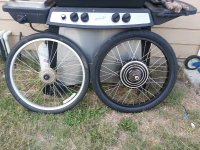
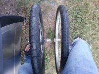
For giggles, I took some pictures comparing the CST Cyclops Pro on the Weinmann DH39 compared to the stock 26x2.125 rear wheel:

Wheel_comparison_side.jpg

Wheel_comparison_top.jpg
 
Looking good!

Keep the posts coming!

Tommy L sends....
mosh.gif
 
Not much progress made lately on the bike... until today! I finally ordered my batteries, wiring, etc from HK. The 4s 20C hard cases are backordered, but hopefully not for too much longer.

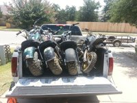
The reason things are taking so long is that I fund my projects with profit from fixing and flipping stuff on Craigslist. I consider that my hobby (since I really enjoy fixing stuff), so do not feel guilty about spending the profits on unnecessary projects, vs using "family" money. It was slow going for a while, $40 here, $60 there... but then I scored a haul of minibikes for $300:

Minibike_haul.jpg

They were all non-running and had been sitting outside for years, but I saw the potential! So far I have fixed and sold three of the four, so that was enough to buy my batteries and get my LBS to order the spokes and lace in my front drum brake. I got the last one running this morning but it needs a new headlight and paint. Once the last one sells, CA and new fork. That should just about be all that I am looking for to finish the initial build and get riding!
 
Batteries came in today, woohoo! They were out of stock for a few days, but once shipped only took 5 days to get here. Now going through 3 charge/discharge cycles per battery with the Hyperion looking for dead cells. I recently set up an old PC in the garage for charging/monitoring (it doubles as my son's Minecraft server), so it is handy to be able to see the pretty graphs.

The only parts remaining to be delivered are my CA and front fork, but at least I can get rocking on the majority of the build. Hope to have her rolling by the weekend! w00t!
 
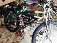
Took a few days of vacation time to enjoy the summer and made some progress on the bike yesterday! Mounted the controller, new springer fork, and front wheel with the 90mm drum brake. I also got the bottom 10 lipos mounted and the mounting tray for the upper two batteries and fuse holder painted. So today I am going to mount the last two batteries and get started on the wiring. The batteries are mounted to the mounting board with a 4" x 2" strip of industrial strength velcro each and zip ties for added security. For the mounting board I used peg board since it is easy to cut and the existing holes make for easy attachment points.

The mounting board itself is attached to the frame with velcro straps, so easy to remove from the bike if I want to charge unmounted.

I will attach a pair of cutters to the bike as well, to clip the zip ties to toss a battery in the case of a thermal event.

BTW, I was shocked to see that none of the lipos I ordered had any dud cells! I ordered one extra just in case, so at least I have a backup should one go south.

(The 5s is for my Mongoose)
Lipos_scaled.jpg

Fork_and_brake_side_scaled.jpg

Fork_and_brake_angle_scaled.jpg

The last two batteries and fuse will be mounted in the open area just below the top bar. The kill switch is mounted below the batteries. I was going to mount it higher, but ended up with en empty area there where it fit perfectly.
Initial_battery_mounting_scaled.jpg
 
Good progress! How's the springer feel?

Protect those RC Lipo but don't seal 'em up and forget 'em - they will change over time so careful cell monitoring is important.
 
Did you order the Hard Packs from Great Britain?

Tommy L sends.....
mosh.gif
 
When I placed the order I only checked the US and HK warehouses and both were out of stock. But since the HK warehouse would allow me to backorder them and have then automatically shipped when they came in, I went with that route. I did not want to risk them coming back in stock in the US warehouse and then missing the window before they sold out again!
 
Ykick said:
Good progress! How's the springer feel?

Protect those RC Lipo but don't seal 'em up and forget 'em - they will change over time so careful cell monitoring is important.

I have not ridden the bike yet with the springer on, but I had the same type of springer fork on my cantilever cruiser framed gas bike and it felt/rode fine. I tighten the tension down pretty good to make them a little less bouncy, but they still soak up some of the bumps and I did not have a problem with high speed wobble at 40 MPH before, so hoping it will behave similarly on this bike. The wheelbase on this frame is a couple inches shorter than my last, so we will see how much of a difference that makes.

And on the lipo front, I definitely want to make some sort of covering to protect the wiring, but nothing too extensive. I keep a cell checker/balancer on the bike and check each battery before a ride and have a handful of lipo buzzers. I am wiring the batteries in 12s 10ah sets, running them as a 24s 10AH pack but charging them as a 12s 20AH pack since my Hyperion only does up to 14s at a time. I only charge about once per week and balance with every charge. But every couple of weeks I plan to charge and balance the individual batteries to make sure all of the cells are still healthy.
 
maurtis said:
When I placed the order I only checked the US and HK warehouses and both were out of stock. But since the HK warehouse would allow me to backorder them and have then automatically shipped when they came in, I went with that route. I did not want to risk them coming back in stock in the US warehouse and then missing the window before they sold out again!

I haven't seen them in stock. So when you placed the B.O. how long did you wait?

Tommy L sends....
mosh.gif
 
I placed the backorder on July 27, they shipped August 2, and arrived here in Kyle, TX on August 7. Shipping was surprisingly quick this time around. My last load of lipos took a bit longer to make it through customs.
 
Aaaaaargh!!! Got everything wired up, connected the batteries... and no fires!

But... the motor spins backwards :cry: The Golden Motor rep said that the wires exited the non-freewheel side and the fellas on the GM forums confirmed that, so it must be a hall/phase combo issue, right?

I am running a Lyen 12fet and tried swapping the yellow and green on the phase and halls, and also tried no swapping. Both run backwards.

I tried #1:

Halls:
B - B
G - Y
Y - G

Phase:
B - B
G - Y
Y - G


Then I tried #2:

Halls:
B - B
G - G
Y - Y

Phase:
B - B
G - G
Y - Y


I know with brushed motors you can just swap the polarity and they usually run fine forwards or backwards. Should I try to fine the magic combo to make this motor run the right direction, or just take it off, swap the freewheel to the other side and flip it?

Thanks!!!
 
On a tip from a post about a conhis motor with the same issue, I swapped yellow and blue halls and yellow and green phases. It runs forward, but stutters.
 
Pick a phase order, then play with halls combinations. One should be it.
 
The wires come out of the freewheel side of the yescomusa 48v 1000W motor. I have both phase and halls hooked up y-g, g-y, b-b on my Hau Tong controller. The wires came out the opposite side for there 48v 500W motor, but hooked up the same way.
 
Back
Top